Leopard 2A6M CAN

Scratchbuilder

Well-Known Member
Joined
Sep 30, 2024
Messages
98
So new forum and to start off my new life here I thought I would start with a Leopard. I could have carried on with some builds I have underway such as the Tiger 1 diorama, but then you would have missed the first half of the builds, and there is nothing more confusing than trying to sort out what was said before and how it was done.
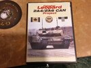
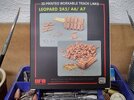
I have the RFM Leopard 2A6M CAN
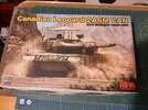
20241005_213951_HDR.jpg
This is to go with the 2A4 CAN version I built some time ago.
Now this like the '4 will have some additions to improve the look of the model, it will have...
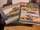
20241005_220106_HDR.jpg
Reference books...
20241005_220114_HDR.jpg
A dvd to pass those hours away while waiting for items to dry...
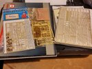
20241005_220308_HDR.jpg
A bit of brass etch to replace a few items and keep the fingers flexible....
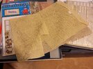
20241005_220324_HDR.jpg
Plus some 'Barracuda' camo netting....
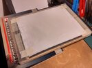
20241005_220422_HDR.jpg
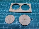
And this - this will be turned into the thermal blanket that goes under the 'Barracuda'....
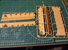
20241005_215805_HDR.jpg
And so the work begins, a bit blurred, but the night is getting on and I need my beauty sleep...
More tomorrow
Cheers
Mike
 
No bad looking Mike. Seated front row. Don't you just love the new car smell this place has and Wow I don't have to have a broom to sweep out the trash before I'm seated. I like it.
 
No bad looking Mike. Seated front row. Don't you just love the new car smell this place has and Wow I don't have to have a broom to sweep out the trash before I'm seated. I like it.
And there I was thinking it was the new underarm stuff after the change from the TCP.
Pleased to have you here holding up the wobbly corner of the bench...
 
Update,
To our American and other cousins, you are going to see words and phrases that seem familiar but are spelt differently, we speak the same language but from different dictionaries, bare with us.
First job today was to take the tissue and soak it in a solution of PVA wood glue and water. Then once the tissue was wet, carefully lifting one side I wiped the excess glue away, re-laid the tissue and repeated on the other side. Finally gently stretching the tissue to get rid of any wrinkles or creases.
This will now dry and it will stick to the glass, but that is intentional and once totally dry can be gently removed from the glass.
Now how to use it????
Cut a piece slightly oversize and place on the area of the model where you want it. Then with a thick (mop) type of paint brush, wet the tissue enough that it becomes workable, and form it to the shape you want, the glue will hold it... Ahhh! I hear you ask, why not do this with the tissue straight onto the model and then apply the glue solution.... Have you ever just sat there and watched your work fall apart, that is what happens, trust me, I cried, a lot.....
Now allow this to dry and once dry gently remove it and then trim it to shape and refit using c/a (superglue) to hold it in place...
OK, that is the basics and we will come back to this with photo's later in the build....
Cheers
Mike.
 
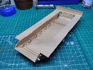
Construction has started on the lower hull with the two sides and floor pan added...
20241006_153929_HDR.jpg
The rear bulkhead was also fitted, but not the inside air intake grills as they will not be seen.
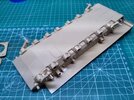
The belly armour was next followed by the four corner suspension arms...
20241006_153910_HDR.jpg
...These are cemented in place so that I avoid the 'dog taking a P' look, aka one leg in the air... The other suspension arms will be cementsed in place but only where the torsion bars fit into the side hull positions, the arms will be left to move and fixed once the model is on its base. With the small locating lugs cut off.
I tend not to follow the instructions and like to get all of the little side assemblies out of the way and then bring the whole together towards the end of assembly...
20241006_153900_HDR.jpg
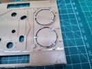
Here I have removed the moulded centre of the left hand air intake, this will be fitted back into the opening but lower down to give some depth to the intake and the etch brass grill and mesh will add to the finished item.
And that is where I am today,
More later
Mike.
 
Update,
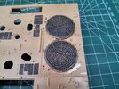
So the air intakes were completed by first cutting them out and cementing them into position lower down to give some depth....
20241008_133659_HDR.jpg
... and painting them matt black and highlighting the raised detail with aluminium paint drybrushed across... Then the first 'spider web' etch was laid acrods the opening and drybrushed again with aluminium, and finall the top mesh was added...
20241008_133647_HDR.jpg
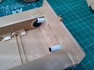
I was not happy to be putting the exhaust mesh over an open hole, so to give it some depth I used two lengths of tube first cemented in place and then secured with some spruglue....
20241008_133633_HDR.jpg
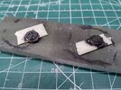
These in turn along with the kit offering of the exhaust grills were painted gloss black followed when dry with ModelMaster Exhaust...
20241008_133623_HDR.jpg
These in turn were cemented to the openings and to close of the open hole....
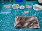
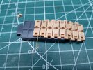
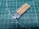
I forgot to mention the track, now when I purchased the Leo, it comes with workable track, BUT, I had also got the 'Buffel' that comes with 'rubber' tracks, and as RFM were offering a 3D printed set of tracks I got those as well, and after putting them away promptly forgot them... So when getting the items together for the initial photos they are missing, but not too worry, I knew I had a set somewhere and after running around like a headless chicken, in one door and out the other, opened a drawer that is clearly marked 'Chieftain tracks' there were the Leo tracks....
20241008_133735_HDR.jpg
And so being used to metal tracks I could see no problems in assembly... and there were none EXCEPT!!!
20241008_133720_HDR.jpg
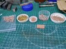
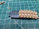
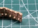
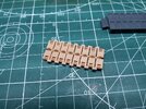
During the curing of the track links, those on the outside will of course cure faster than those in the centre, and what that leads to is the holes for the brass wire to fit through closing up slightly, and slightly means enough to stop the wire passing through. So out of that little lot you now see - 64 have got to be driiled out to the correct size, BUT, yo have to be carefull removing the links because the centre connector is also printed between each link.....
20241008_133713_HDR.jpg
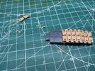
And there you see the start of assembly except the track jig does not fit and you end up with a five hand juggling act, which is where the original tracks came into being - I robbed the track jig(s) from that set which are a little better. Now from left to right you have (damaged) track pads, brass rods, centre connector, good track links and finally end connectors and be carefull which way up and which way they fit.
So all in all, not a bad days work for 3 hours....
And today it will be out with the JD, on with the AC/DC tracks on the go and earwax loosened.....
Cheers
Mike
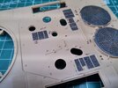
Nearly forgot, also started to add the non slip to the non slip pads...
20241008_134143_HDR.jpg
 
Looks like you're having a lot of fun there Mike - the improvement to the intakes and exhausts is excellent. Just out of interest, what did you use to attach the PE to the top of the intakes? I did something similar with the Tiger 1 I'm building and made a bit of a mess of it.

That block of track links looks like a bad bit of print design to me - I know they have to maximise print space, but that does seem a very odd arrangement to me. The potential to cut the wrong thing, or as you said, not to cure properly seems huge.
 
Tracks - I think I am about to pull out any remaining hair I have including nasal hair and the other... I am having to drill out every connector as well as the track links I mentioned before... 3D tracks I thought great! no more messing about with cleaning up metal ones, forget it, these are more a PITA than any metal tracks. By now I would have at least one length done, RFM you have not read the manual on 3D printing, go back and start again.

Attaching the mesh grills. I placed the first one on the opening and then used a small metal block to hold it in position, made any adjustments and then with an old #10A scalpel blade (any other would do) ran some c/a around the edge just by touching it to the metal and letting the capillary action drag it underneath the join. And once dry remove the block and then do the same on those edges.
This save trying to hold the model steady with one hand, position and hold the mesh with the other hand and apply the c/a with your mouth...
 
I've never tried it, but a tip I heard about might help you.

You can buy staples (they come in many sizes) and bend one of the 90-degree angle straight then use the other end to insert in place of the rods. The square nature of the staple binds with the plastic/resin (sometimes the rods are too lose and can slip), and that bent part (not 100% straight) also helps keep them in place.
 
Update

So still playing with the tracks.... Tried different ways to build them from using the provided jig, to stealing the jig from another set, and finally ending up with just one of the jgs from another plastic set, and even then it does not totally fit....

The assembly process is as follows, first the tools I have put together...

20241012_151204_HDR.jpg
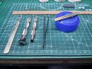
Above the assembled track is the jig I am using, then from left to right - scalpel #10A blade for getting rid of the little niblets that are left. Drill with 0.6mm drill fitted for cleaning out the holes, drill with one of the connecting rods to check the holes are clear or need drilling, flat tweezers but with 240 wet n dry paper at the tips (10mm length) so that the small parts do not vanish, and vanish they will. Finally is an old plastic jar top that has been heated up and an old metal ball pushed into it to make a c/a cup - and on top of that an old wooden peg half with a dressmakers pin that has been shaped into a chisel shape for applying the c/a....

20241012_141852_HDR.jpg

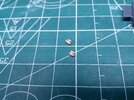
This is what I mean by the parts being fragile, the top one is what it is supposed to be and the lower one is where I tried to clean it out with the drill, the other half never to be seen again....

20241012_141838_HDR.jpg
Here we have the parts ready to be joned together, the rods have been fitted into the link halves...
20241012_141940_HDR.jpg
the middle connector is in place abd the rod pushed through...
20241012_142006_HDR.jpg
The second link is then attached and the rod again pushed through, there needed to be some movement of the link to get the rod to go through the middle connector....
20241012_142041_HDR.jpg
And if you get this far then all that is required is the end connectors to be pushed onto the rods, making sure they are the correct way about...
20241012_142218_HDR.jpg
And then with the pin just touched into the c/a it is touched onto the end of the rods - you do not need to soak the end connectors...
20241012_142342_HDR.jpg
And this is what you should end up with - only another 100+ to go.......
I have not neglected the main vehicle, it is just a case of sticking on the parts that can go on before the camoflague 'Barracuda', but some pics will be coming...
 
Ooh, those look like fun. Not. May I recommend the Trumpeter Leopard 2 tracks if you ever find yourself building one of these tanks again? They go together much more easily than it looks like these do, with pins moulded to the ends of the blocks.
 

Latest posts

Back
Top