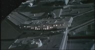
The Battlestar Galactica Moebius should have made!

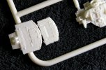
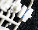
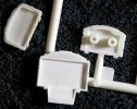
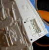
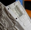
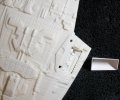
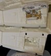
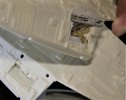
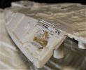
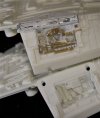
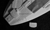
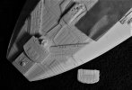
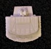
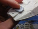
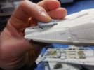
Hello everyone! I've got a thread of this build at The RPF also. There are a few fellow modelers following along with me there and a fine gentleman named "Analyzer", sent me a "Shapeways" bridge. Thank you very much Mr. Analyazer. I told hime I would do a direct comparison to the diferreneces from the original kit part and the "Shapeway" part.

There IS no comparison. AT all, except they are both bridges for the MOEBIUS Battlestar Galactica.

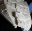
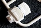
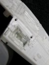
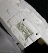
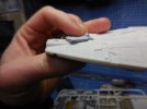
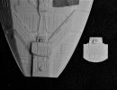
Here is that comparison just in case no one has ever seen these compared:

DSCN0372.jpgDSCN0373.jpgDSCN0374.jpg

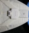
Here, is the one I posted way back at the beginning of this thread as to what I had done with some modifications. STILL, no comparison.DSCN0376.jpg

Stuck temporarily where it goes.

DSCN0377.jpgDSCN0378.jpg

DSCN0375.jpg
 
Last edited:
Now, back to the build itself...

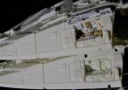
I decided those trenches just below the spank brand new 8-Rad parts could use screwing up, so off I went!

Here's the original parts taped into place:

DSCN0379.jpgDSCN0380.jpgDSCN0381.jpg
DSCN0382.jpg

I totally started from scratch with a couple new trench boxes.

DSCN0383.jpg

Here's where I took this. Just as an aside note, this was the tiniest fiddling so far. The TIP of the brush for TAMIYA Extra Thin is larger than 95% of the parts in these pictures and practically every part had to be either scratch built or are modified from NO LESS than 15 ERTL/ESCI 1/76 kits, 2 TAMIYA Waterline ships, an AIRFIX Scammel Tank Transporter, an AIRFIX HMS Belfast, A 1/1200 Revell Bismarck, several AIRFIX HO tank and truck kits and at LEAST 37.6 miles of stretched sprue.

DSCN0384.jpgDSCN0385.jpgDSCN0386.jpgDSCN0387.jpgDSCN0388.jpg
 
Last edited:
Great man... Just amazing.

I seriously think it's more work to 'correct' something like this than it is to scratch it from the beginning.

But incredible work none the less.

I always wonder why they didn't give it more of a battleship feel, some big ass guns and stuff.

I'm fact... I ones thought so much about it, that I ended up modeling my version of the Galactica. I don't wanna steal your thread so I'll link to it here

Here

I hope it's OK, if not let me know, I'll remove it.
 
Great man... Just amazing.

I seriously think it's more work to 'correct' something like this than it is to scratch it from the beginning.

But incredible work none the less.

Thank you Mr. BLT! It may have very well been better to scratch the whole thing. Those "trenches" have burned up TWO weekends.

I always wonder why they didn't give it more of a battleship feel, some big ass guns and stuff.

I'm fact... I ones thought so much about it, that I ended up modeling my version of the Galactica. I don't wanna steal your thread so I'll link to it here

Here

I hope it's OK, if not let me know, I'll remove it.

Yes sir it's OK! Add away my friend!
 
Yeah... Back in my 3dsMax days.

The new BSG was all the rage back then, and for some reason the design partet the waters, so I figured I'd design my version of it. Never finished, but it, and my viper got a lot of attention.

Anyway, those details look sick man, keep it up.
 
Yeah... Back in my 3dsMax days.

The new BSG was all the rage back then, and for some reason the design partet the waters, so I figured I'd design my version of it. Never finished, but it, and my viper got a lot of attention.

Anyway, those details look sick man, keep it up.

Still got my attention too! Great work!

And... Thank you!
 
Hi Rob,
I do not have any pictures, but instead I've been building this kit on my YouTube channel.

It shows my work on a breadboard to create an LED chaser circuit using a 555 chip and a 4017 chip together for the chase light sequences for the hangar bays' landing runways. Here's the link to Elonic's helpful how-to video I followed:


The problem is that this is supposed to run on 9V, but I can only get the results when I power it down to 5V. It might be because I am not using as many lights as the Elonics guy? I'm usually pretty good at understanding Indian accents, but he mumbles a bit. Once I can get this to work, I will provide you with the best information as I can, and draw a diagram that even a non-electronics guy like myself can understand because I really don't understand what I am doing.

I wanted to learn how to do this sort of thing because those pre-built timers tend to be expensive. My friend in San Diego just gave me two Tena Controls chips for use on Enterprise models though, so now I am curious to play with those. I already found a schematic to use a 556 timer chip to use on Enterprise models though, as it controls the blinking nav lights and the anti-collision strobes simultaneously. These Tenacontrol chips are nice, but I still want to muster the courage to figure out these things on my own. One more diagram I have is for lighting a Trek-style torpedo launch bay and I want to try that out on my 350 K'Tinga kit.
Greg
 
Ok Mr. Steve! I see you have a whole series of this build going. I'll be back after I watch them all and catch up.
 
Hi Rob,
I do not have any pictures, but instead I've been building this kit on my YouTube channel.

Yes sir, you do! Watched. Studied. Absorbed. Rewatched.

It shows my work on a breadboard to create an LED chaser circuit using a 555 chip and a 4017 chip together for the chase light sequences for the hangar bays' landing runways. Here's the link to Elonic's helpful how-to video I followed: (Link removed for this reply only).

The problem is that this is supposed to run on 9V, but I can only get the results when I power it down to 5V. It might be because I am not using as many lights as the Elonics guy? I'm usually pretty good at understanding Indian accents, but he mumbles a bit. Once I can get this to work, I will provide you with the best information as I can, and draw a diagram that even a non-electronics guy like myself can understand because I really don't understand what I am doing.

Agreed. Very much mumblification, unfortunately. For me, it's more than just mumbling, I can't even catch some of the things UN-mumbled.

Try and see if THIS video can help?


Easier to understand for me AND, you already have the components you'll need to try his way with what you've made already? This video shows it working just the way we want IN a 9 volt configuration.

The following, in no way, is meant to be derogatory AT ALL, so DON'T take it as such. You and I both will be trying these things and there are things to be aware of, as you said and just because I mention something, doesn't mean you don't know already. Now, I'm sure you're aware that SOME components have an orientation, right? By that I mean they can be placed in a "wrong" direction and won't work properly, if at all. Always check. There are ALSO voltage ranges on many of these components too, so be sure there as well.

I wanted to learn how to do this sort of thing because those pre-built timers tend to be expensive. My friend in San Diego just gave me two Tena Controls chips for use on Enterprise models though, so now I am curious to play with those. I already found a schematic to use a 556 timer chip to use on Enterprise models though, as it controls the blinking nav lights and the anti-collision strobes simultaneously. These Tenacontrol chips are nice, but I still want to muster the courage to figure out these things on my own. One more diagram I have is for lighting a Trek-style torpedo launch bay and I want to try that out on my 350 K'Tinga kit.
Greg

As you've undoubtedly seen, there are several configurations for making us a "chaser circuit". Some, don't use either the 555, the 4017 or either. The "Tenacontrols" stuff, from what I understand, is good stuff, but as you've mentioned, anything ready to go out of the package, won't be cheap. This sort of thing is the one thing I've always noticed being that way. All the components to make this chaser cost $2 bucks (You know what I'm saying) but to buy one made already cost you $75. Definitely all "paying for the knowledge" on this one.

I can tell you one thing here. We will get a working circuit. One of my best friends here in the real world is an Electronics Engineer. Like you say, it would be GREAT to know how to do some of this stuff, but if all fails, we'll cheat.

;)

Rob.
 
And Steve, I've noticed something that you pointed out in one of your videos that I've never seen mentioned, Thank you!

Right here:

DSCN0372.jpg

I too, as I mentioned earlier, have been given access to a "Shapeways" bridge which was sent to me. In your video, you've shown that it doesn't quite fit exactly where it's suppose to on the MOEBIUS Galactica without some maneuvering. I'm looking into that today.
 
Ok, Mr. Steve's video has brought me to this...

Has anyone used the Shapeways bridge on their Galactica build? If y'all have, can you chime in here with some thoughts? I've been foolin' around with the one Mr. Analyzer sent me and I seem to have a problem. I watched "stevethefish.net's youtube video where he is using it and it appears that I'm not the only one to notice this, but it's too big? When it's placed where it goes on the model, it extends either far too forward or far too rearward, depending on which way you wanna go? Can some of y'all that have used this tell me what y'all found out with it?
 
Here's what I'm talking about.

Here's my modified bridge placed where it goes. Now, although nowhere near as detailed as the shapeways part, it IS in scale with the studio model.

dscn0392-jpg.jpg


Here, we have the shapeways bridge in place. As close as I can anyway, because that lump behind the bridge would need to be removed to mount this piece properly, but I can show what I mean with this. In this picture, I have it placed where it will have to go along the forward edge. As you can see, it goes well beyond the detail piping.

dscn0393-jpg.jpg


Here, I have it placed forward and lined up with the rear where it would have to go and as can be seen here, it extends much too far forward.

dscn0394-jpg.jpg


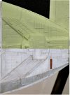
Here, as I sorta posted during the review earlier, is my modified bridge directly on top of the shapeways part. That shapeways part would have to be almost the exact same size to look proper on this model?

dscn0398-jpg.jpg
 
The following, in no way, is meant to be derogatory AT ALL, so DON'T take it as such. You and I both will be trying these things and there are things to be aware of, as you said and just because I mention something, doesn't mean you don't know already. Now, I'm sure you're aware that SOME components have an orientation, right? By that I mean they can be placed in a "wrong" direction and won't work properly, if at all. Always check. There are ALSO voltage ranges on many of these components too, so be sure there as well.
You're not being derogatory at all. I get plenty of derogatory comments on YouTube, particularly from armchair modelers who say I don't know what I am doing (which I never claimed otherwise) and they have zero content of their own to provide the community. I just share what I do and seek feedback from people who can give advice without being dickbrains about it. So far, the worst in my experience are Trek modelers. Their attitude is "be a perfect professional modeler or GTFO," as their expectation is that their time is so extremely precious that only the best modelers should dare provide modeling video content.

So as to the circuit, I think what I should do is take it apart and do it all over again. I must have missed something. In the video, it seems to work just fine at first, but then later it's somehow different. I have no idea what happened, so I should just start all over again because sometimes that fixes it.

What I will need to do is drill holes into the Paragraphix photoetch for those landing strip chase lights. I have the mini shuttles from JD Graphics and a friend of mine has actually sculpted tiny Vipers in the same scale. (He hasn't sent them to me yet, and I've been waiting for a few years already...)

As for the Shapeways bridge, IIRC I filed the detail down on the top of the model down so that the back of that bridge deck can fit. I think I might place some styrene or something to fill in where it overhangs the raised detail. The bridge is translucent, so I plan to place a few warm white SMDs up through the holes there to light it up. All I'll have to do is just sand down the raised details where the lights need to go.
 
Thank you Mr. Steve! You are welcome to build with me anytime sir, except that I won't be a "perfect professional modeler" in any way. I can't. Provide me with any kinda content you want. I'm grateful for it.

Yes sir, doing your circuit one more time can't hurt. I've watched a few of the same circuit at this point and they all seem to be very similar and you're using a breadboard for testing, so no harm done! Plug and re-plug to your heart's content. Now, once you strike gold with it, drop what you did right here for me too. Like I said, if all else fails, we got a ringer over here and he'll actually SHOW us what to do to get what we need. He's already said he would, so we're ultimately set. I do, however, just like yourself, need to do whatever I can to figure it out before I call in the big dog.

Tiny, for Vipers in scale, would certainly describe it. Show 'em to me here when you ever get 'em, please. Zoom in.

As far as that bridge goes, there are several discrepancies involved with the fit of that, both with the bridge and the model itself. I've been fiddling with that for a couple days now doing some comparisons.

Here's just an example:

shapebridge.jpg

What that is, is the studio scale Galactica and the Moebius model scaled side by side with the shapeways bridge in place toward the rear aligned where it needs to be at the front edge.

The bridge is too large and the model nose is too long. No way around that, but I do have a plan. I raised that nose strip the very first step of this build. I'll remove it once again, trim it as I need to so that the details line up better with the studio model and go from there. We'll see.
 
It looks like you can just move it forward a bit, after removing that circular protrusion which is currently in front of the bridge. It won't be a perfect match, of course, but good enough for me. I might pull out my shelf queen and take a look at it tonight when I get home from work an hour from now.
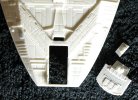
 
It looks like you can just move it forward a bit, after removing that circular protrusion which is currently in front of the bridge. It won't be a perfect match, of course, but good enough for me. I might pull out my shelf queen and take a look at it tonight when I get home from work an hour from now.

Yes sir, please do! I'm finoodling wid it now.

DSCN0409.jpg
 
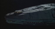
Alright, this evening I'm taking a look at my Galactica model. Let's compare how that part sits down as compared to the filming miniature.

002.jpg
DSCN7032.JPG
It points down and cannot sit flush. Whoever designed this part really did not make it so that it can just plop into place easily.

028.jpg
DSCN7033.JPG
It needs to be raised up somehow to get it to stand up straight.

DSCN7034.JPG
Well, that is just too high. The detail is nice, but it just isn't made to fit onto the model properly. Maybe if I can just sand the kit bridge way down so that it is just used as a pedestal for the Shapeways part, it won't slope downwards and sit straight?

Now check this out. 308 Bits has made a newer version made for lighting. It looks mostly the same, but it has a pedestal to bring it up more.
https://www.shapeways.com/product/F...idge-drilled?optionId=67929086&li=marketplace
 
Last edited:

Latest posts

Back
Top