You are using an out of date browser. It may not display this or other websites correctly.
You should upgrade or use an alternative browser.
You should upgrade or use an alternative browser.
Messerschmitt Bf 109 G-14 (Zoukei-Mura 1:32)
- Thread starter Edbert
- Start date
Edbert
Well-Known Member
- Joined
- May 16, 2024
- Messages
- 896
Not terrible. I think 1/32 is why it wasn't a nightmare, took a few breaks and wore the magnifiers. Used super-pointy (tech term) tweezers and an old airbrush needle to thread them through buckles.Those look great, we'll done. I hear ya about the eyes, me too. Besides that, how hard were they to put together? A real pain in the a$$, or not to bad?
Edbert
Well-Known Member
- Joined
- May 16, 2024
- Messages
- 896
I made progress!
Engine is about 90% done, cockpit about 60%.
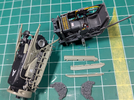
I need to do more work on the engine before taking pictures. Overall I am happy with the cockpit, I mixed some yellow with my gold as recommended here (looks like I added some gold to my yellow but nevermind that), but when I was trying to decide how to add spice with colored warheads on those 30mm Mk.108 rounds...I realized I was about to cover them up.
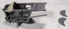
You might notice above that the RLM66 is a bit thin on the two dashboards, I'll try to shoot them another dose tonight so they can cure over the next 24h.
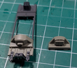
Here's more detail of the unfinished bits, the entire top section is dry-fitted, but that is a testimony to the fit of this kit.
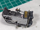
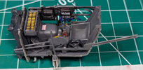
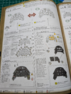
While the instructions are clear, arguably the best I've ever seen, it is easy to make mistakes. Note the two different parts for the only two aircraft in the box. The G-14 and the "White one" or U4 variant.
Speaking of instructions, I intend to work tomorrow on the instrument panel, and only that.
Engine is about 90% done, cockpit about 60%.

I need to do more work on the engine before taking pictures. Overall I am happy with the cockpit, I mixed some yellow with my gold as recommended here (looks like I added some gold to my yellow but nevermind that), but when I was trying to decide how to add spice with colored warheads on those 30mm Mk.108 rounds...I realized I was about to cover them up.

You might notice above that the RLM66 is a bit thin on the two dashboards, I'll try to shoot them another dose tonight so they can cure over the next 24h.
Here's more detail of the unfinished bits, the entire top section is dry-fitted, but that is a testimony to the fit of this kit.


While the instructions are clear, arguably the best I've ever seen, it is easy to make mistakes. Note the two different parts for the only two aircraft in the box. The G-14 and the "White one" or U4 variant.

Speaking of instructions, I intend to work tomorrow on the instrument panel, and only that.

Last edited:
Edbert
Well-Known Member
- Joined
- May 16, 2024
- Messages
- 896
Dashboard or instrument panel time.
I was really leaning towards the decals behind the clear plastic method, seems logical that it would look more like the real thing. But in reality, I decided on the other approach after applying just a few decals.
Problems with using the clear part versus the opaque:
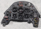
I think the visibility of the gauges when applied on top of an opaque/painted surface are just so much better, that alone decides it for me.
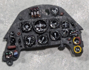
This is after applying a blob of gloss to each face, still need to chrome some screws that will probably not be visible. Along with a reminder how small this is to begin with, 1/32 sounds large, but theBf109 was a small aircraft.
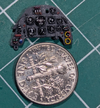
I was really leaning towards the decals behind the clear plastic method, seems logical that it would look more like the real thing. But in reality, I decided on the other approach after applying just a few decals.
Problems with using the clear part versus the opaque:
- This one I blame on the manufacturer, but the decals had the adhesive on the wrong side
- As a result getting them aligned perfectly was nearly impossible, at least extremely fiddly
- The thickness of the thin clear plastic makes the gauge faces dark and too recessed

I think the visibility of the gauges when applied on top of an opaque/painted surface are just so much better, that alone decides it for me.

This is after applying a blob of gloss to each face, still need to chrome some screws that will probably not be visible. Along with a reminder how small this is to begin with, 1/32 sounds large, but theBf109 was a small aircraft.

Last edited:
Edbert
Well-Known Member
- Joined
- May 16, 2024
- Messages
- 896
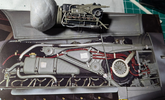
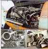
I'm so tempted to try this, thought it was wiring but looking closer it appears to be fluid lines. probably under pressure. I know the vapor filters and some rubber bits needs to be painted black even if I decide to not do the plumbing. The problem is, I'm past the point where I committed to having raised cowlings, so there's no going home.

Edbert
Well-Known Member
- Joined
- May 16, 2024
- Messages
- 896
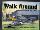
The picture is from the "Walk Around" series of book from Squadron-Signal, it shows a LOT of variants though. All were "Gustav" but in the majority of the pictures the coolant tanks were silver, seems the G14 and later G10 (wait wut?) used RLM02...usually.
You did a crazy excellent job on the instrument panels. I don't think I could do all those individual tiny decals. I think it looks great!Dashboard or instrument panel time.
I was really leaning towards the decals behind the clear plastic method, seems logical that it would look more like the real thing. But in reality, I decided on the other approach after applying just a few decals.
Problems with using the clear part versus the opaque:
This is what I mean about the printing being on the wrong side, the high-resolution printed side is up as in normal decals. But these are required to go behind the clear, so they would NOT stick, I spent 20 minutes working on one pod of 4 dials, using micro-set and micro-sol as adhesive. I set it down carefully to dry and it looks like it slipped a bit. It could also be caused by the deep recess, but depending on the angle of viewing they look like they are skewed to one side or the other. The thick (according to scale, it is really thin) plastic also made the gauges look darker. It will be hard to see inside the cockpit and underneath the hood anyway.
- This one I blame on the manufacturer, but the decals had the adhesive on the wrong side
- As a result getting them aligned perfectly was nearly impossible, at least extremely fiddly
- The thickness of the thin clear plastic makes the gauge faces dark and too recessed
View attachment 129259
I think the visibility of the gauges when applied on top of an opaque/painted surface are just so much better, that alone decides it for me.
View attachment 129258
This is after applying a blob of gloss to each face, still need to chrome some screws that will probably not be visible. Along with a reminder how small this is to begin with, 1/32 sounds large, but theBf109 was a small aircraft.
View attachment 129260
Jakko
Well-Known Member
- Joined
- Oct 9, 2024
- Messages
- 615
You mean the red and black hoses? They look like some kind of fluid lines, but even after looking through some real Bf 109 handbooks online I can't find what they're for. Most of those were not for a G, so maybe they weren't present on other variants? The E doesn't seem to have had the triangular tank under the engine support or the tear-drop shaped one inside it either, for example.
plastickjunkie
Active Member
- Joined
- May 27, 2010
- Messages
- 121
That was the best paint I've used in all of my years modeling. They airbrush extremely well and are fantastic. Unfortunately they have been discontinued for some knucklehead reason.At my age, with failing eyesight, I have no time to spend fighting with fit, more than what should always be expected. If that means spending more money, so be it, but this kit cost less than or no more than the 1/32 Corsair and 1/48 F-4B from Tamiya.
I'm hoping this complexity with so many details and the large assembly manual will help me slow down.
My decision for now is...do I use my old RLM colors in enamel with the acrylic wash?
View attachment 126882
Andy the Sheep
Active Member
- Joined
- Oct 7, 2024
- Messages
- 38
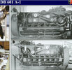
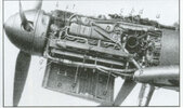
Edbert, after a fast email exchange with a friend of mine who's a real Me 109 fan I have what could be the answer to your doubt about those red and black lines.
They are the 2 ways ducts to the supplementary oil tank the Gustavs had behind the spinner. They were originally rubber (black) or metal. The colours in the pic you published are a consequence of the modern tubes used in refitting the engine.
Some pics here below
Andrea
They are the 2 ways ducts to the supplementary oil tank the Gustavs had behind the spinner. They were originally rubber (black) or metal. The colours in the pic you published are a consequence of the modern tubes used in refitting the engine.
Some pics here below


Andrea
Edbert
Well-Known Member
- Joined
- May 16, 2024
- Messages
- 896
Dminor, thanks man!
Jakko, yes those red/black lines in the photograph. I believe this is a picture of a Museum restoration and I think they take some liberties with materials and coloration. The red parts appear to be part of a loom to prevent chafing of the actual (black) hoses. The photograph is from a "Walk Around" book by Squadron, I've trusted them for decades, but exceptions exist.
PlasticJunkie, total agreement, in addition to the quality of the paint I appreciated them having RLM and FS #s on the bottle! I think it was Rust-Oleum that purchased Testors then killed the brand off. I don't understand that at all. I mean, if you do not want to continue to make the stuff fine, sell it don't just kill it.
Andrea, WOW, thanks for the backup, and your friend. I think you are correct, not only the red part is inaccurate but also the conduit surrounding the lines. I'm going to have a go at creating a few and see what it looks like. Looking at detailed pictures resulted in me changing the colors on the last part of the plug wires too. Zoukei Mura says to paint them silver, so I did, but most pictures show a light tan/bronze muted color on the last part by the plugs. I think it was a sort of heat shield but that is just a guess.

Last edited:
Pantherman
Well-Known Member
- Joined
- Feb 10, 2022
- Messages
- 3,690
Cool, excellent info. PanthermanEdbert, after a fast email exchange with a friend of mine who's a real Me 109 fan I have what could be the answer to your doubt about those red and black lines.
They are the 2 ways ducts to the supplementary oil tank the Gustavs had behind the spinner. They were originally rubber (black) or metal. The colours in the pic you published are a consequence of the modern tubes used in refitting the engine.
Some pics here below
View attachment 129750View attachment 129751View attachment 129752
Andrea
Edbert
Well-Known Member
- Joined
- May 16, 2024
- Messages
- 896
I've not been updating the progress, but I've been working very slowly yet steadily. I'm still going to say that the detail of this kit is about as good as anything I've ever seen, and the fit is very precise, in fact a coat of paint (x2 - on both sides of the part) was enough to make the fuselage halves not quite meet. Easy to remove the paint from those surfaces, needed to anyway for the glue. Just saying it is an example of the fit. I did find what I consider to be a flaw though, made worse by my lack of skill, but bad enough to make me say this is for a more advanced builder, certainly to the advanced side of experienced.
I had minor issues with the rear vertical stab, if you count the horizontal stabs, the elevators, the rudder and actuators...there were 19 parts involved. Yes, just the exterior tail surfaces, I'm not counting the control rods and actuators hidden inside the bodywork. It all fit, so that is not the problem, but without spending a lot of time dry-fitting it would have been a mess.
But the bigger problems I had were in attaching the wings. The wings themselves went together great.
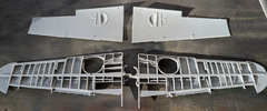
This picture was in preparation of painting RLM02 on the inner surfaces.
The main spar of each wing extends far enough (along with some hoses and lines) into the body, this makes locating them pretty easy, but they make for a very wobbly assembly while you attach outer skin parts to solidify everything.
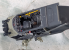
In the above picture you can see two different sub-assemblies that extend outboard of the cockpit. The rear one is for the wing spars, you inset each wind until the little hole (the RLM66 part above) lines up and you know it is the right spot. The front assembly in RLM02 is for the main landing gear which must be installed prior to attaching wings. So you have the wobbly assembly with parts sticking out that make it hard to hold/handle and to allow for cement drying.
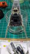
But it is the exterior parts that gave me trouble, I could get everyone of them to fit, but not all at the same time. No matter what I moved where to close a gap, I created another one. I will take the blame, I think the kit is just better than I am. But I spent almost 2 hours fiddling with it before I decided it would not be perfect and got the glue out. I do think it was a bit over engineered though.
So not counting the cockpit assembly shown above, or the wings and landing gear struts, there were seven (!!) separate pieces of external sheet-metal to seal it up. I think that is just too complex for an intermediate-skilled builder to handle.
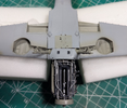
Only the front lower section shown above is glued, there were three parts to make that section, but the rest of the sheetmetal is dry, just illustrating the small gaps all around the roots. I was able to easily press the parts into place and apply some extra-thin, but I had to maintain pressure to keep the joins correct, but sealing this section up correctly resulted in large gaps on the upper side.
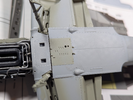
So my decision was to seal the leading edges well, as well as the underside of the wings to the large center part, but I decided to leave the gap shown here, just to make the gaps on the top not as severe. They are about the same size, I'll show them later.
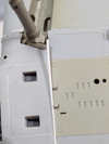
Then I could insert some shaved evergreen-styrene into the gap. I DESPISE putty! And part of my construction will be obscured by the drop-tank mounting system. This left only two more parts to be applied to cover the top portion of the wing-roots.
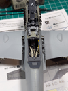
The above picture shows a lot actually. You can see the top of the landing gear, the part of the wind-spar that enters under the cockpit, the oil-cooler lines that I wimped out on and did not paint, etc.
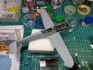
Here you can see upper covers installed and the gaps I was complaining about. But so far this is the only real problem I've had.
I got the front of the cowling, the oil-cooler exhausts, the flaps and the ailerons done too.
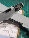
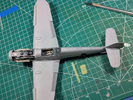
I had minor issues with the rear vertical stab, if you count the horizontal stabs, the elevators, the rudder and actuators...there were 19 parts involved. Yes, just the exterior tail surfaces, I'm not counting the control rods and actuators hidden inside the bodywork. It all fit, so that is not the problem, but without spending a lot of time dry-fitting it would have been a mess.
But the bigger problems I had were in attaching the wings. The wings themselves went together great.

This picture was in preparation of painting RLM02 on the inner surfaces.
The main spar of each wing extends far enough (along with some hoses and lines) into the body, this makes locating them pretty easy, but they make for a very wobbly assembly while you attach outer skin parts to solidify everything.

In the above picture you can see two different sub-assemblies that extend outboard of the cockpit. The rear one is for the wing spars, you inset each wind until the little hole (the RLM66 part above) lines up and you know it is the right spot. The front assembly in RLM02 is for the main landing gear which must be installed prior to attaching wings. So you have the wobbly assembly with parts sticking out that make it hard to hold/handle and to allow for cement drying.

But it is the exterior parts that gave me trouble, I could get everyone of them to fit, but not all at the same time. No matter what I moved where to close a gap, I created another one. I will take the blame, I think the kit is just better than I am. But I spent almost 2 hours fiddling with it before I decided it would not be perfect and got the glue out. I do think it was a bit over engineered though.
So not counting the cockpit assembly shown above, or the wings and landing gear struts, there were seven (!!) separate pieces of external sheet-metal to seal it up. I think that is just too complex for an intermediate-skilled builder to handle.

Only the front lower section shown above is glued, there were three parts to make that section, but the rest of the sheetmetal is dry, just illustrating the small gaps all around the roots. I was able to easily press the parts into place and apply some extra-thin, but I had to maintain pressure to keep the joins correct, but sealing this section up correctly resulted in large gaps on the upper side.

So my decision was to seal the leading edges well, as well as the underside of the wings to the large center part, but I decided to leave the gap shown here, just to make the gaps on the top not as severe. They are about the same size, I'll show them later.

Then I could insert some shaved evergreen-styrene into the gap. I DESPISE putty! And part of my construction will be obscured by the drop-tank mounting system. This left only two more parts to be applied to cover the top portion of the wing-roots.

The above picture shows a lot actually. You can see the top of the landing gear, the part of the wind-spar that enters under the cockpit, the oil-cooler lines that I wimped out on and did not paint, etc.

Here you can see upper covers installed and the gaps I was complaining about. But so far this is the only real problem I've had.
I got the front of the cowling, the oil-cooler exhausts, the flaps and the ailerons done too.


Last edited:
Edbert
Well-Known Member
- Joined
- May 16, 2024
- Messages
- 896
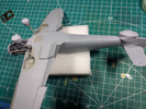
I ran out of space to post the last picture, so went long with another post.
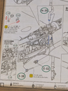
I have cut and painted some wires/hoses to replicate the picture from the book. But the engine needed to be mounted to connect them correctly and the kits provided parts to connect them too as well that I still need to install. But I'm not giving up on that idea, although they will not be red as in the picture.
Here's those two little bits I'm talking about, E-38 & E-52.
Edbert
Well-Known Member
- Joined
- May 16, 2024
- Messages
- 896
Seeking opinions...reviews say the decals are good with this kit. And I do not need to do the "tulip" nose, which is a PITA.
But at least for the main insignia, should I do my 1st ever paint-job (I'll need to buy a masking set, but I have time), or stay modest and use the decals?
But at least for the main insignia, should I do my 1st ever paint-job (I'll need to buy a masking set, but I have time), or stay modest and use the decals?
mustang1989
Active Member
- Joined
- Aug 6, 2022
- Messages
- 114
WOW!! ZM doesn't leave a thing out of their kits do they? I'll be bookmarking this one now that I've found it Edbert. Beautiful looking crate dude.
I just hope they'll release a 1/48 version of this at some point. I'll be all over that like a Rat on a Cheeto!!
I just hope they'll release a 1/48 version of this at some point. I'll be all over that like a Rat on a Cheeto!!
Wow! That is an insane amount of detail. I don't know if I could get through a kit that detailed. I must say I am very impressed with your patience and tenacity in that build. I would have been frustrated trying to get it all together and making it look as good as you have.
