Messerschmitt Me-329

Papermodder

Modeller in both Plastic and Paper Card
Joined
Jan 2, 2013
Messages
1,224
Greetings.
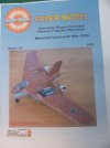
For this years BSC I have decided to build the Messerschmitt Me-329 Heavy Fighter / Bomber.
Only a plywood mockup and a glider version were ever built. Several variants were envisioned but never got past the drawing board.

I am using GreMir Models 1/33 kit for this project.
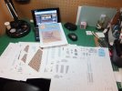
BSC2014Start_zps641545f8.jpg

CoverPage_zpsc79bd013.jpg

I may try my hand at vacuforming a canopy for this build. We'll see.

Good luck to all participants.

Jim
 
Thank you Patrick.
I haven't built an aircraft in quite a while, so it is a little bit out of my comfort zone. But, have been itching to build one for a while now.
Always liked the concept aircraft, where imagination and creativity are allowed into the physical realm. I think this is the same bug for my love of sifi.

Jim
 
First update.
It doesn't seem like a lot, but first thing first.
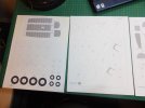
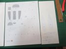
The parts requiring reinforcing are laminated on to 1mm heavy card, and have to be let to dry for 24hrs in a press to keep them flat.

HeavyCard1_zps666dc106.jpg

HeavyCard2_zps5e08d83b.jpg

Cutting parts out of heavy card is a pain. I have a couple of ideas to try to see if it makes it easier. We'll have to see if it works, if not then it's back to cutting them out with a knife. ::)

Thank you for following.
Questions & comments are always welcome.

Jim
 
Hello.
Tonight's update.
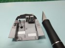
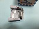
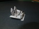
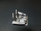
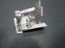
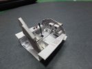
I've started on the cockpit. This has to be built first and installed into the front end superstructure, then the rest of the craft is built around it.
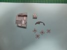
Though it does not look like much, this is still several hours of construction. The IP is 2 layers of card laminated. The IP support wall is laminated to heavy 1mm card.

Cockpit1_zpse1f86cee.jpg

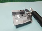
The assembled IP is then attached to the base interior.
The quadrant as shown in the kit was to be mounted straight vertical. Upon viewing actual pics of the real cockpit it was found that they were canted toward the inside of the cockpit, which makes them easier to handle. This required the sticks to be modified from stock. Being only a couple of mm in size these were a little touchy to handle and install. In-fact one of the small black ones flicked out of the tweezers never to be seen again, and had to be remade.
The control stick had no boot, so one was made.
This is where I am at tonight.

Cockpit2_zps01cdea76.jpg

Cockpit3_zpsd8fb41dd.jpg

Tomorrow we will start on the seats and the rudder petals.

Thank you for following.
Questions and comments are welcome.

Jim
 
Very cool. How do you print this stuff, on heavy stock on a laser printer or something? The joystick looks like it would have been a pain!
 
Hi Cave Dweller.
I print the templates what ever card I require from 20lb to 110lb. My printer is a HP D7260 6 ink inkjet.
The joystick was actually very simple. Just a piece of wire with a short piece of 20lb printer paper wrapped around the wire for the grip. The boot is just 3 paper circles punched out of 110lb card with different size punches. This is all glued together,painted, then glued in position.
Hope this helps.

Jim
 
Great start. I love to see that Luft '46 stuff being built. Very cool.
 
Good evening.
Moving ahead on this build, I started working on the rudder petals.
The assembly drawing with this kit is a little vague on some of the assemblies and am glad I found the photos of the aircraft. They are a big help. Other points will have to go on educated guesses and imagination.
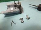
The pedals were assembled and the supports cut from wire.

Cockpit4_zpse68c610e.jpg

Using a needle, punch the location for the pedals as you cannot easily but glue wire to card. A mounting hole is much easier and more secure.

Cockpit5_zps8752e317.jpg

Cockpit6_zpsd6d71871.jpg

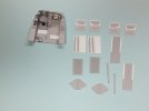
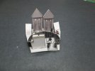
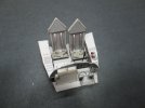
Next up is the construction of the seats. Here you can see the main parts for the seats. There are a couple of parts that have to be folded and laminated before assembly can start.

Cockpit7_zpsd5037bc5.jpg

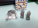
The seats actually went together quite well. The most tedious part was cutting out all the belts, as well as the through slots in the back of the seats. Then glue them in place.

Cockpit8_zps8128fc82.jpg

Cockpit9_zpsc6393b5d.jpg

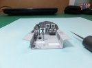
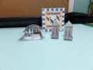
The completed seats were then glued into position. I found my small square helpful to hold the seats upright and in position to dry, as they were a little top heavy.
This is where I am at tonight.

Cockpit11_zps16aa31e8.jpg

Cockpit12_zps38fad071.jpg

Cockpit14_zpsa6365eae.jpg

Cockpit15_zps44027007.jpg

Cockpit16_zpsf2cb0bac.jpg

Cockpit17_zpsd55eacd9.jpg

This completes this stage of the build.
Next up is the construction of the front section of the fuselage.

Thank you for following.
Questions and comments are welcome.

Jim
 
Hi Patrick. Thank you.
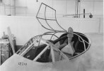
From the photos I've seen of the real aircraft this is how ME layed it out.

Me_329_-3_zps0b8ed615.jpg

Jim
 

Latest posts

Back
Top