My Another 1/350 TOS Enterprise Build Thread
- Thread starter trekriffic
- Start date
trekriffic
Well-Known Member
- Joined
- Jan 6, 2012
- Messages
- 1,040
Today's update from work done yesterday...
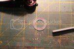
I wanted to see if I could approximate the ceiling soffit which illuminated the peirmeter of the bridge so I cut out a ring from clear styrene sheet and sanded it to help with light diffusion. The inner diameter was made to be about 1/16" less than the upper hull dome opening:
A ring was made from Evergreen strip and glued to the inner edge. The width of the ring matched the distance from the bottom of the lighting soffit and the underside of the dome openng above:
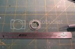
Reflective tape was wrapped around the inner edge of the ring to reflect light back inside the soffit and block light from showing thru the ring:

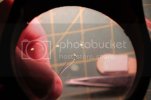
For the upper dome lighting I soldered two 30 AWG kynar wires to a warm white surface mount LED I got from Lighthouse LEDs. This was my first time soldering to such tiny LEDs; guess my experience working with the small crew figures was good practice:
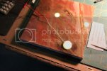
The surface mount LED was epoxied to a styrene disc which was then glued into the underside of the translucent white upper dome. Here it is lit up:
I used the "N" wiring harness for which there are two sockets on the circuit board. These are optional ports intended for those who want to light the impulse engines but I won't be lighting those on my build so I used one socket for the dome light instead.
The upper dome in place on top of B-C deck and lit up:
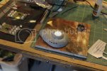
The ceiling soffit ring is glued into the hull with CA:
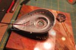
The bridge is glued to the soffit ring with CA :
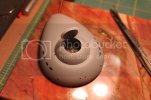
The "O" lighting harness is installed and tested:
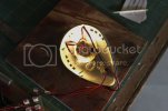
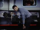
"Captain. You may want to look at this. It appears to be a miniature of our bridge."
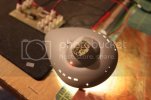
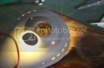
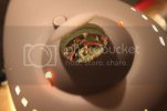
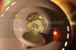
After these pics were taken I went a step further and inserted small squares of semi-opaque milk jug plastic between the three LEDs and the bridge displays and main viewscreen to help diffuse the light more. Then this morning I mixed up some Envirotex resin and poured it around the bridge inside A deck up to the level of the LEDs. The clear resin helped to alleviate hot spots and more evenly distribute light around the bridge displays. It was a small but noticeable improvement.
Thanks for following along!
I wanted to see if I could approximate the ceiling soffit which illuminated the peirmeter of the bridge so I cut out a ring from clear styrene sheet and sanded it to help with light diffusion. The inner diameter was made to be about 1/16" less than the upper hull dome opening:

A ring was made from Evergreen strip and glued to the inner edge. The width of the ring matched the distance from the bottom of the lighting soffit and the underside of the dome openng above:

Reflective tape was wrapped around the inner edge of the ring to reflect light back inside the soffit and block light from showing thru the ring:

For the upper dome lighting I soldered two 30 AWG kynar wires to a warm white surface mount LED I got from Lighthouse LEDs. This was my first time soldering to such tiny LEDs; guess my experience working with the small crew figures was good practice:

The surface mount LED was epoxied to a styrene disc which was then glued into the underside of the translucent white upper dome. Here it is lit up:

I used the "N" wiring harness for which there are two sockets on the circuit board. These are optional ports intended for those who want to light the impulse engines but I won't be lighting those on my build so I used one socket for the dome light instead.
The upper dome in place on top of B-C deck and lit up:

The ceiling soffit ring is glued into the hull with CA:

The bridge is glued to the soffit ring with CA :

The "O" lighting harness is installed and tested:

"Captain. You may want to look at this. It appears to be a miniature of our bridge."


After these pics were taken I went a step further and inserted small squares of semi-opaque milk jug plastic between the three LEDs and the bridge displays and main viewscreen to help diffuse the light more. Then this morning I mixed up some Envirotex resin and poured it around the bridge inside A deck up to the level of the LEDs. The clear resin helped to alleviate hot spots and more evenly distribute light around the bridge displays. It was a small but noticeable improvement.
Thanks for following along!
ModelMakerMike
"It's Slobberin' time""
- Joined
- May 28, 2011
- Messages
- 1,838
It looks incredible, and stuff! ;D ;D ;D ;D
trekriffic
Well-Known Member
- Joined
- Jan 6, 2012
- Messages
- 1,040
Thanks Guys!
Next up... the launch bay!
After removing the parts from the sprue I cleaned up with a file and sanding sticks:
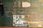
I'll mask off the ceiling, side and rear wall windows from inside before I paint the floor and walls. My plan for the ceiling, side and rear walls is to paint them silver on the inside followed by black and a coat of primer. The silver on the inside will relect light back outwards thru the clear plastic towards the windows on the side of the hull. I'll paint the final colors before applying the PE which will be painted before gluing to the plastic.
The launch bay taped toether for dry fitting into the hull:
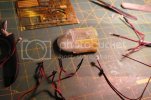
I had to enlarge the slots in the floor (the lighting kit doesn't include a floor as you are supposed to use the kit part) so the sidewalls tabs would fit flush. On the rear of the sidewalls I had to file a little off the tab that fits between the pair of LED brackets on each side of the rear wall.
Once I had all the wire harnesses in place and taped to the bay I did a second dry fit. The first test I did without the wiring was perfect. Everything went together with no gaps. With the wiring in place it was not quite so good. There was a 1/16" gap between the hull halves caused by not enough clearance between the LED's, the wiring and the hull itself. I could force it closed but I have no intention of gluing the hull halves together with the rear seam under constant stress so... I'll have to make some modifications to the wiring scheme. The LEDs appear to be wired in parallel so the board must be supplying 3 volts to each string. Perfect! One thing I'm going to do for sure is switch out the wire for a smaller gauge-probably the 30 AWG Kynar I just got. That alone might do the trick along with grinding and thinning the square LED that fits over the hangar doors. I'm also not going to install the LEDs in the trenches in the ceiling as those will be covered with PE; the ceiling beams are not meant to be lit in my opinion. I'm going to use thin SMD LEDs over the ceiling on top of the bay. If there's not enough clearance I may have to go ahead and thin the top of the hull plastic just a little so they fit.
Stay tuned!
Next up... the launch bay!
After removing the parts from the sprue I cleaned up with a file and sanding sticks:

I'll mask off the ceiling, side and rear wall windows from inside before I paint the floor and walls. My plan for the ceiling, side and rear walls is to paint them silver on the inside followed by black and a coat of primer. The silver on the inside will relect light back outwards thru the clear plastic towards the windows on the side of the hull. I'll paint the final colors before applying the PE which will be painted before gluing to the plastic.
The launch bay taped toether for dry fitting into the hull:

I had to enlarge the slots in the floor (the lighting kit doesn't include a floor as you are supposed to use the kit part) so the sidewalls tabs would fit flush. On the rear of the sidewalls I had to file a little off the tab that fits between the pair of LED brackets on each side of the rear wall.
Once I had all the wire harnesses in place and taped to the bay I did a second dry fit. The first test I did without the wiring was perfect. Everything went together with no gaps. With the wiring in place it was not quite so good. There was a 1/16" gap between the hull halves caused by not enough clearance between the LED's, the wiring and the hull itself. I could force it closed but I have no intention of gluing the hull halves together with the rear seam under constant stress so... I'll have to make some modifications to the wiring scheme. The LEDs appear to be wired in parallel so the board must be supplying 3 volts to each string. Perfect! One thing I'm going to do for sure is switch out the wire for a smaller gauge-probably the 30 AWG Kynar I just got. That alone might do the trick along with grinding and thinning the square LED that fits over the hangar doors. I'm also not going to install the LEDs in the trenches in the ceiling as those will be covered with PE; the ceiling beams are not meant to be lit in my opinion. I'm going to use thin SMD LEDs over the ceiling on top of the bay. If there's not enough clearance I may have to go ahead and thin the top of the hull plastic just a little so they fit.
Stay tuned!
trekriffic
Well-Known Member
- Joined
- Jan 6, 2012
- Messages
- 1,040
Quaralane said:Truly jaw-dropping work with that bridge and lighting
Thaks a lot Q-man!
Based on a suggestion form a member on another forum I revised how I lit the dome on top of the bridge. Using the existing wires on "A" deck I soldered two brass strips to form contacts:
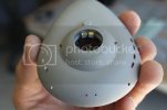
These match up with two brass strips mounted at the edge of the dome which I completely redid:
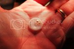
Now I can remove the dome completely to view the interior of the bridge rather than having it attached by flimsy 30 AWG wires that can break.
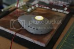
Here's the dome lit up with it's new contacts:
Getting back to the shuttle bay...
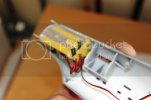
Here's the taped together bay in the stern with the rear wall and fantail LED wiring harness in place but not the upper LEDS for the ceiling and beacon light:
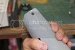
The hull went together fine with little need to try and force the halves together:
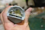
The fit wasn't so good though after I tried installling the bay with the ceiling lights in place; I ended up with about a 1/32 inch gap in the upper hull and stern. I think I can fix that though using SMD LEDs and filing down the thickness of the rectangular beacon LED over the doors. I'll also remove the kit wires and use something thinner like 26 or 30 AWG.
Switching gears, I masked off the areas of the shuttle bay that I either wanted left clear or that I would be applying CA to in order to glue the brass photo-etch in place. Then I sprayed Testors silver on the inside of the walls to reflect light from the rear wall LEDs outwards towards the inside surface of the hull to hopefully illuminate the rear windows on either side of the bay:
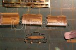
After the silver dried I left the masks on and sprayed with Tamiya grey primer:
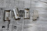
Yesterday I airbrushed with Model Master Sand:
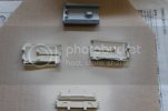
Next I'll mask the Sand areas of the walls off and airbrush with MM Dark Ghost Grey. I'll also paint the PE before gluing it to the inside walls.
Then it'll be checking for light leaks and applying PPP and more paint as needed.
Moving on while the paint dries I took a gander at the strobe lights that came with the lighting kit.
Ports "P" on the main PC board in the secondary hull are meant to power the strobe lights in the stern.
When I plugged the wires in though I noticed one flashed at a slow rate, similar to the saucer flashers, while the other one barely flashed at all!
Cripes! This woudl not do!
Then I had a brilliant idea.
Years ago I had purchased a dual synchronized strobe flasher board from my LHS:
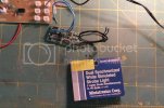
It's powered by 9-15 volts which is perfect for this project. The bulbs are incandescent and tiny; I believe they are referred to as grain-of-rice bulbs.
I powered the board up for the first time and the bulbs flashed very quickly, just like I saw on TV!
I also noticed an open port on the PC board; it's the one in the lower righthand corner which is an unassigned port.
I checked it and written below the port it lists it as a 12V LED strip port which is great because it gives me an easy way to plug in the strobe board using one of the unused N harnesses from the saucer.
I will fit the strobe flasher in right behind the shuttle bay with room to spare and I think it will look much better than the strobes from the lighting kit.
One thing I'm wondering though is if it would be possible to swap out the incandescent bulbs for LED's. Does anyopne know if that's possible with this board? Would it just be a matter of adding a resistor for each LED?
One last thing to mention before getting back to work, if you are looking to use a different approach for attaching the power supply plug into the kit base or a custom base of your own and would rather plug it into a panel jack rather than using the harness in the lighting kit with it's mating inline coupler, what you want is a size "M" panel jack. I had one that I got years ago at Radio Jack and it fits perfectly to the power supply plug. It will fit really nicely into a hole I'll drill into the refit Enterprise base. I have a 1/350 Reft kit which was the first issue with the rectangular "drydock" base. I'll use it instead of the round base from the kit which I'll swap out and be using for the refit at some point. The panel jack has solderable contacts in the rear which I'll split two circuits off from to light the LEDs and the motors separately with rocker switches.
Anyway, that's it for now.
Thanks for watching my progress!
ModelMakerMike
"It's Slobberin' time""
- Joined
- May 28, 2011
- Messages
- 1,838
;D ;D
trekriffic
Well-Known Member
- Joined
- Jan 6, 2012
- Messages
- 1,040
Grendels said:It should be possible to just swap an led for the grain of rice bulbs. The trick will be in finding the right voltage. If I had to guess this board is probably voltage in = voltage out
Actually I checked with Miniatronics and they told me it's 1.5V at 30mA going to each bulb so it doesn't sound like a swapout is possible since the LED's need 3V at 20mA.
letsgobrowns82
Active Member
- Joined
- Feb 27, 2011
- Messages
- 1,368
Wow that's a lot of work. Looks great though
Grendels
Active Member
- Joined
- Nov 24, 2009
- Messages
- 9,092
trekriffic said:Grendels said:It should be possible to just swap an led for the grain of rice bulbs. The trick will be in finding the right voltage. If I had to guess this board is probably voltage in = voltage out
Actually I checked with Miniatronics and they told me it's 1.5V at 30mA going to each bulb so it doesn't sound like a swapout is possible since the LED's need 3V at 20mA.
That surprises me, because every time I have dealt with grain of rice bulbs they have been 12 to 15 volts. Must be a voltage regulator there somewhere....
trekriffic
Well-Known Member
- Joined
- Jan 6, 2012
- Messages
- 1,040
Update...
I've spent the past few days working on the upper bridge dome, the shuttle bay, and the shuttle itself.
For the bridge dome I wanted to add some interest to the underside.
I figure no one ever saw the actual ceiling of the bridge so I was free to add whatever I wanted.
For starters I drew a geometric design on some scrap sheet styrene.
I also cut a hollow disc from Evergreen tubing to go in the center.
A rhinestone fit inside the disc very nicely:
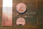
I also found some decals in my stash that looked like gold screening which I cut out and applied to the front of the housings around the "A" deck contacts. I know they liked the look of screens on the original series so it fit into my sense of the design ethos back then:
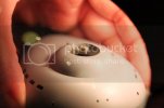
The finished underside of the bridge dome. I went with a grey and red color scheme to match the look of the bridge below.
I also used the gold screen decals in the center pie sections:
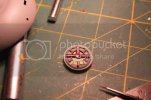
I had two rectangular rare earth magnets that looked like they might fit inside the shuttle cavity:
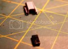
Sure enough, they were a perfect fit:
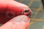
I glued the second magnet to the underside of the shuttle bay floor using Devcon 5-Minute Epoxy:
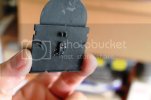
I noticed there were no landing pads on the shuttle so I cut the heads off some small pins and glued them into holes drilled into the front underside of the nacelles:
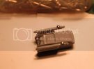
For the rear landing strut I bent a pin near the head and cemented it into a hole drilled into the stern undercut:
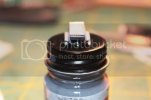
The shuttle in profile. It has just the right degree of tilt now I think.
The magnet inside really grabbed the cap on this bottle of paint... or needle files... or pins... or tweezers... or any ferrous metallic surface:
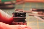
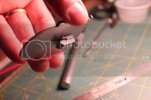
As you can see here, the shuttle can be placed on the floor of the bay and held upside down without fear of falling due to the attraction between the magnet inside it and it's mate under the shuttle bay floor:
Moving on, for the shuttle bay parts, I masked off the sand colored areas on the walls and airbrushed them with a 50/50 mix of Dark Ghost Grey and Neutral Grey. Then I removed the tape on the windows and brushed them with fluorescent white acrylic paint. This included the ceiling too:
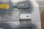
I've already painted the photo etch parts with the 50/50 grey mix and will glue them to the walls and ceiling next.
Thanks for reading!
I've spent the past few days working on the upper bridge dome, the shuttle bay, and the shuttle itself.
For the bridge dome I wanted to add some interest to the underside.
I figure no one ever saw the actual ceiling of the bridge so I was free to add whatever I wanted.
For starters I drew a geometric design on some scrap sheet styrene.
I also cut a hollow disc from Evergreen tubing to go in the center.
A rhinestone fit inside the disc very nicely:

I also found some decals in my stash that looked like gold screening which I cut out and applied to the front of the housings around the "A" deck contacts. I know they liked the look of screens on the original series so it fit into my sense of the design ethos back then:

The finished underside of the bridge dome. I went with a grey and red color scheme to match the look of the bridge below.
I also used the gold screen decals in the center pie sections:

I had two rectangular rare earth magnets that looked like they might fit inside the shuttle cavity:

Sure enough, they were a perfect fit:

I glued the second magnet to the underside of the shuttle bay floor using Devcon 5-Minute Epoxy:

I noticed there were no landing pads on the shuttle so I cut the heads off some small pins and glued them into holes drilled into the front underside of the nacelles:

For the rear landing strut I bent a pin near the head and cemented it into a hole drilled into the stern undercut:

The shuttle in profile. It has just the right degree of tilt now I think.
The magnet inside really grabbed the cap on this bottle of paint... or needle files... or pins... or tweezers... or any ferrous metallic surface:

As you can see here, the shuttle can be placed on the floor of the bay and held upside down without fear of falling due to the attraction between the magnet inside it and it's mate under the shuttle bay floor:

Moving on, for the shuttle bay parts, I masked off the sand colored areas on the walls and airbrushed them with a 50/50 mix of Dark Ghost Grey and Neutral Grey. Then I removed the tape on the windows and brushed them with fluorescent white acrylic paint. This included the ceiling too:

I've already painted the photo etch parts with the 50/50 grey mix and will glue them to the walls and ceiling next.
Thanks for reading!
danimal518
New Member
- Joined
- Nov 9, 2012
- Messages
- 80
This is absolutely amazing! I can't wait to see what else you do and especially the finished model.
trekriffic
Well-Known Member
- Joined
- Jan 6, 2012
- Messages
- 1,040
Update...
ParaGrafix PE was attached to the walls and ceiling. PPP was then applied between the observation booth PE window frames and later retouched with the 50/50 grey mix to block light leaks. PPP was also used to bring the frame edges up to the level of the slanted lower surfaces of the booths. Basically I wanted the frames to look integrated with the booths.
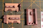
The back wall and floor:
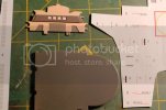
The floor was sprayed with Tamiya Ocean Gray 2 which is very close to the color of the 50/50 mix.
The walls and ceiling were sprayed with Testors Glosscote in preparation for decaling:
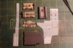
I also sprayed the shuttle with Tamiya Light Ghost Grey.
Prior to that I extended the rear landing strut so it is more in line with the bottom of the rear of the nacelles.
Oh... and there are lots of decals for the shuttle too:
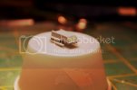
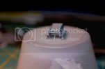
For the nacelles I'll paint them a slightly darker tone using Testors Light Ghost Grey and a touch of black (or maybe steel).
Or if one of my other grey paints is a little darker I'll just use that.
I must have a half dozen shades of grey in my stash right now.
ParaGrafix PE was attached to the walls and ceiling. PPP was then applied between the observation booth PE window frames and later retouched with the 50/50 grey mix to block light leaks. PPP was also used to bring the frame edges up to the level of the slanted lower surfaces of the booths. Basically I wanted the frames to look integrated with the booths.

The back wall and floor:

The floor was sprayed with Tamiya Ocean Gray 2 which is very close to the color of the 50/50 mix.
The walls and ceiling were sprayed with Testors Glosscote in preparation for decaling:

I also sprayed the shuttle with Tamiya Light Ghost Grey.
Prior to that I extended the rear landing strut so it is more in line with the bottom of the rear of the nacelles.
Oh... and there are lots of decals for the shuttle too:


For the nacelles I'll paint them a slightly darker tone using Testors Light Ghost Grey and a touch of black (or maybe steel).
Or if one of my other grey paints is a little darker I'll just use that.
I must have a half dozen shades of grey in my stash right now.
trekriffic
Well-Known Member
- Joined
- Jan 6, 2012
- Messages
- 1,040
Here are a few pics of what I finihsed yesterday and this evening...
There are two harnesses labelled "M" for connecting the saucer board to the single 5MM flasher LEDm on each side of the saucer at the 3 and 9 o'clock positions. The LED sits sideways between the holes top and bottom where you insert the plastic domes for the flashing formation lights. As is, the LED is bright enough but it's not pointed directly up or down to get the most illumination shining thru the plastic inserts so... I cut off the LED on each harness and spliced in two clear 2mm lighthouse LEDs wired in parallel purchased from Modeman Tom's website, Modeler's Brand Hobby Supplies.
Here's the link to his site:
http://modelersbrand.com/
The board is providing 5V so no resistors are needed.
These LED's have long round narrow flat-topped necks that are the perfect size to fit thru the upper dome hole; just drill or route out a matching diameter sized cavity in the red and green domes provided in the lighting kit and insert the LED up thru the hull and cement into the plastic dome. For the lower flasher you would drill a matching cavity partway into the smaller clear part and then insert the kit part thru the hull in the lower saucer.
Anyway, in this pic you can see the lighting kit harness on top and my retro-fitted harness below. I now have separate dedicated flashers for each dome light top and bottom on each side:
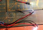
Here are the shuttle bay walls and floor. Only the Galileo shuttle, back wall and floor have been decalled at this point:
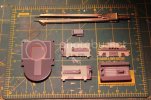
The back wall:
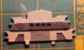
The shuttle:
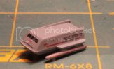
Tomorrow I should be able to finish the wall decaling and assemble the bay.
There are two harnesses labelled "M" for connecting the saucer board to the single 5MM flasher LEDm on each side of the saucer at the 3 and 9 o'clock positions. The LED sits sideways between the holes top and bottom where you insert the plastic domes for the flashing formation lights. As is, the LED is bright enough but it's not pointed directly up or down to get the most illumination shining thru the plastic inserts so... I cut off the LED on each harness and spliced in two clear 2mm lighthouse LEDs wired in parallel purchased from Modeman Tom's website, Modeler's Brand Hobby Supplies.
Here's the link to his site:
http://modelersbrand.com/
The board is providing 5V so no resistors are needed.
These LED's have long round narrow flat-topped necks that are the perfect size to fit thru the upper dome hole; just drill or route out a matching diameter sized cavity in the red and green domes provided in the lighting kit and insert the LED up thru the hull and cement into the plastic dome. For the lower flasher you would drill a matching cavity partway into the smaller clear part and then insert the kit part thru the hull in the lower saucer.
Anyway, in this pic you can see the lighting kit harness on top and my retro-fitted harness below. I now have separate dedicated flashers for each dome light top and bottom on each side:

Here are the shuttle bay walls and floor. Only the Galileo shuttle, back wall and floor have been decalled at this point:

The back wall:

The shuttle:

Tomorrow I should be able to finish the wall decaling and assemble the bay.
ModelMakerMike
"It's Slobberin' time""
- Joined
- May 28, 2011
- Messages
- 1,838
;D
Similar threads
- Replies
- 0
- Views
- 81
- Replies
- 2
- Views
- 183
- Replies
- 0
- Views
- 752
Latest posts
-
-
-
-
-
CANADIAN VERSION AMT 1971 Dodge Charger Muscle Car! $37.00 Shipped!!
- Latest: SuperheroSanctum
-
-
