Grendels
Active Member
- Joined
- Nov 24, 2009
- Messages
- 9,092
Hello all,
I finally found the time to start posting my progress on my build for the contest. The N.S.E.A Protector from Galaxy Quest.
I decided to light this model, and I am going to use various techniques to do so. The first thing I started on was drilling holes:
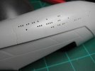
I am going to use fiber optics to light this part of the ship so I won't have to worry that much about light leak.
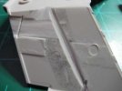
After I drilled the holes, I set those parts aside and started to work on the wings. This is the part that would be the most difficult to light. I can't use fiber optics for the engines, nor for the windows in this part of the model. The windows are rectangular and too large for fiber. (I do have fiber in that size, but it is not rectangular, and it is so stiff, that I could never get it strung through the wings to the light source.) So I drilled out the windows, and started working on light block.
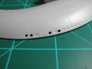
Since that photo was taken, I have squared up the windows, and masked them off. I have also drilled out the windows in both wings.
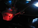
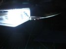
After drilling out the windows, I started working on the LED's for the lights. The engines are a very small area and will suffer from hot spots if I am not careful. (I may not be able to avoid them, the only sure way is to stuff the thing full of LED's and there just isn't room in this model the way it is designed.) Most LED's are designed to focus the light into a spot instead of spreading it out like a normal light bulb would. To compensate for this, I sanded down the tops of most of the LED's to a point:
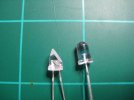
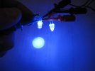
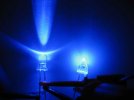
As you can see in the photos, this does spread out the light more, instead of focusing it on one point.
I then gave the ship a coat of flat black for a primer. This serves two purposes: First to block light from the interior of the model. (The traditional way of applying light block paint is on the inside of the model, I just chose the outside for this mainly for reason number two.) And the second reason is that the black paint will allow me to see any scratches on the model and fix them before the final coats of paint are applied.
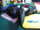
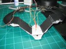
Once done, I started to apply the reflective strips of aluminum tape to the inside of the model. The windows on the wing will be hard to light directly with an LED. The wings are just not thick enough for the LED to fit. So I am going to have to place the LED at a distance and get it to bounce over to the windows.
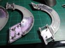
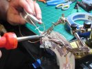
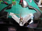
In the above photo I am soldering the LED's in place to light the forward engines, and the wing windows. You can see that the foil tape serves two purposes, one to reflect light, and two to hold the wires in place instead of using glue. This tape is really easy to work with.
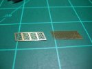
I then turned my attention to the engine intakes. I had purchased the photo etch set from Paragraphix for this build and it came with some brass inserts to replace the molded details. So those details had to go:
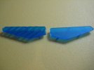
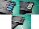
Here are a couple of shots of the parts with and without the brass inserts:
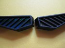
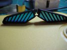
I think it looks much better with the brass than without. It also has an added benefit that when the lights are turned off, you see a metallic grid behind the grates, but when the lights are turned on, all you see is a blue glow. I don't have any photos of this at the moment, but will have them by the contest deadline.
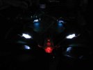
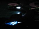
Below is a lighting test, sorry for the blurry photo, but I was too lazy to get out the tripod for the camera. I have also added some fiber optic position lights since then. The model indicates these with bumps, and some of them are not in the proper locations. I moved them to match the screen stills I have from the movie.
The wings also have red lights along the leading edge of the wing in two locations. I am going to light these with fibers, mainly because the parts themselves are only 0.75 mm thick. The smallest LED I have is 3mm, and I know that they make smaller, I just didn't want to mess with trying my hand at surface mounted LED's. A couple of photos of the process:
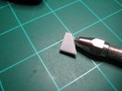
Fibers glued in place. WARNING: if you ever work with fiber optics, do not use CA glue it melts the fibers, or makes the brittle
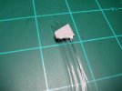
After this, I started working on getting the wires from the wings to the body of the ship. I had to cut two groves in the wings for the wires to fit:
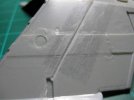
The fibers will run through the wings just fine without this step.
After that was done, I started working on the command ship. I want this lighted, but I also want to remove it from the model as the kit was designed. So I have to do a few modifications. First step was to cut out the windows on the ship. I didn't want to cut them all out, so that it would have a "lived" in look to it. Also, these windows are really small about the width of a standard hobby knife blade. The braces between them are equally small, and I was afraid of weakening the models structure too much. If I were to glue it in place, then this concern would not really be an issue, but it will get handled from time to time and I don't want it to fall apart one day.
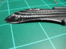
The command ship is attached to the model with magnets. These magnets are quite strong for their size, and hold the ship firmly in place. (Warning, the magnets are mentioned in the instructions, but they do not show where they go. It is pretty easy to figure it out if you just take a look at the parts.) The photo etch set comes with brass pieces for the command ship, I intend to use them as an interface between power and the lights when the ship is attached. Current will be transfered with two pins passing through the hull.
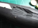
I don't think I will be able to hide those pin heads too much. Reducing their size will damage the brass on the command ship. (scratch it up.) And the raised surfaces on the pins will help the parts make better contact.
3mm LED's fit in the command ship just fine, and I am going to use two of them to supply the light. I have not done this part yet, and it is on todays to do list.
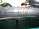
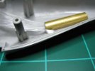
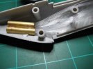
As for the main body of the ship. I glued in place a few lengths of brass tube:
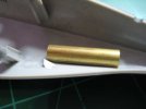
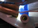
This tubing will be the hub for the fiber optics. I am using one on each side of the ship to make later assembly easier. Each side of the ship will have between 45 and 50 fibers coming out of it. Each of these tubes can handle that number of fibers just fine. There are two benefits to using the tubes. First, the trap all of the light, reducing light leak, and second, they focus the light all on the fibers which is exactly what I want.
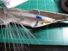
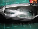
Here are a couple of photos of the fibers being installed:
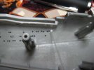
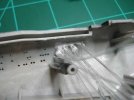
Right before I started this post, I glued in the last of the fibers to the main body. All I have left is one more light can for the red lights in the wings, and I can start gluing parts together. Once accomplished, a little bit of masking, and then I can paint her.
I have also done some work on the base for the model, and will be my focus this week. I have some surprises there, and will post them as soon as they are worthy of photos.
I finally found the time to start posting my progress on my build for the contest. The N.S.E.A Protector from Galaxy Quest.
I decided to light this model, and I am going to use various techniques to do so. The first thing I started on was drilling holes:

I am going to use fiber optics to light this part of the ship so I won't have to worry that much about light leak.
After I drilled the holes, I set those parts aside and started to work on the wings. This is the part that would be the most difficult to light. I can't use fiber optics for the engines, nor for the windows in this part of the model. The windows are rectangular and too large for fiber. (I do have fiber in that size, but it is not rectangular, and it is so stiff, that I could never get it strung through the wings to the light source.) So I drilled out the windows, and started working on light block.

Since that photo was taken, I have squared up the windows, and masked them off. I have also drilled out the windows in both wings.
After drilling out the windows, I started working on the LED's for the lights. The engines are a very small area and will suffer from hot spots if I am not careful. (I may not be able to avoid them, the only sure way is to stuff the thing full of LED's and there just isn't room in this model the way it is designed.) Most LED's are designed to focus the light into a spot instead of spreading it out like a normal light bulb would. To compensate for this, I sanded down the tops of most of the LED's to a point:


As you can see in the photos, this does spread out the light more, instead of focusing it on one point.
I then gave the ship a coat of flat black for a primer. This serves two purposes: First to block light from the interior of the model. (The traditional way of applying light block paint is on the inside of the model, I just chose the outside for this mainly for reason number two.) And the second reason is that the black paint will allow me to see any scratches on the model and fix them before the final coats of paint are applied.

Once done, I started to apply the reflective strips of aluminum tape to the inside of the model. The windows on the wing will be hard to light directly with an LED. The wings are just not thick enough for the LED to fit. So I am going to have to place the LED at a distance and get it to bounce over to the windows.


In the above photo I am soldering the LED's in place to light the forward engines, and the wing windows. You can see that the foil tape serves two purposes, one to reflect light, and two to hold the wires in place instead of using glue. This tape is really easy to work with.
I then turned my attention to the engine intakes. I had purchased the photo etch set from Paragraphix for this build and it came with some brass inserts to replace the molded details. So those details had to go:

Here are a couple of shots of the parts with and without the brass inserts:


I think it looks much better with the brass than without. It also has an added benefit that when the lights are turned off, you see a metallic grid behind the grates, but when the lights are turned on, all you see is a blue glow. I don't have any photos of this at the moment, but will have them by the contest deadline.
Below is a lighting test, sorry for the blurry photo, but I was too lazy to get out the tripod for the camera. I have also added some fiber optic position lights since then. The model indicates these with bumps, and some of them are not in the proper locations. I moved them to match the screen stills I have from the movie.

The wings also have red lights along the leading edge of the wing in two locations. I am going to light these with fibers, mainly because the parts themselves are only 0.75 mm thick. The smallest LED I have is 3mm, and I know that they make smaller, I just didn't want to mess with trying my hand at surface mounted LED's. A couple of photos of the process:

Fibers glued in place. WARNING: if you ever work with fiber optics, do not use CA glue it melts the fibers, or makes the brittle

After this, I started working on getting the wires from the wings to the body of the ship. I had to cut two groves in the wings for the wires to fit:

The fibers will run through the wings just fine without this step.
After that was done, I started working on the command ship. I want this lighted, but I also want to remove it from the model as the kit was designed. So I have to do a few modifications. First step was to cut out the windows on the ship. I didn't want to cut them all out, so that it would have a "lived" in look to it. Also, these windows are really small about the width of a standard hobby knife blade. The braces between them are equally small, and I was afraid of weakening the models structure too much. If I were to glue it in place, then this concern would not really be an issue, but it will get handled from time to time and I don't want it to fall apart one day.

The command ship is attached to the model with magnets. These magnets are quite strong for their size, and hold the ship firmly in place. (Warning, the magnets are mentioned in the instructions, but they do not show where they go. It is pretty easy to figure it out if you just take a look at the parts.) The photo etch set comes with brass pieces for the command ship, I intend to use them as an interface between power and the lights when the ship is attached. Current will be transfered with two pins passing through the hull.

I don't think I will be able to hide those pin heads too much. Reducing their size will damage the brass on the command ship. (scratch it up.) And the raised surfaces on the pins will help the parts make better contact.
3mm LED's fit in the command ship just fine, and I am going to use two of them to supply the light. I have not done this part yet, and it is on todays to do list.
As for the main body of the ship. I glued in place a few lengths of brass tube:

This tubing will be the hub for the fiber optics. I am using one on each side of the ship to make later assembly easier. Each side of the ship will have between 45 and 50 fibers coming out of it. Each of these tubes can handle that number of fibers just fine. There are two benefits to using the tubes. First, the trap all of the light, reducing light leak, and second, they focus the light all on the fibers which is exactly what I want.
Here are a couple of photos of the fibers being installed:


Right before I started this post, I glued in the last of the fibers to the main body. All I have left is one more light can for the red lights in the wings, and I can start gluing parts together. Once accomplished, a little bit of masking, and then I can paint her.
I have also done some work on the base for the model, and will be my focus this week. I have some surprises there, and will post them as soon as they are worthy of photos.

