You are using an out of date browser. It may not display this or other websites correctly.
You should upgrade or use an alternative browser.
You should upgrade or use an alternative browser.
Now… Voyager…
- Thread starter trekriffic
- Start date
greyphantom1000
Active Member
- Joined
- May 19, 2011
- Messages
- 214
Can someone answer a question about this kit? I'm thinking about starting one and I'm wondering why the detail at the top of the saucer is usually removed and the photo etch put in its place? All the parts behind the bridge. I'm looking at mine and the detail is crisp, why do most ppl replace it with the photo etch? Thanks!
trekriffic
Well-Known Member
- Joined
- Jan 6, 2012
- Messages
- 1,010
My understanding is the molded panels are too thick.Can someone answer a question about this kit? I'm thinking about starting one and I'm wondering why the detail at the top of the saucer is usually removed and the photo etch put in its place? All the parts behind the bridge. I'm looking at mine and the detail is crisp, why do most ppl replace it with the photo etch? Thanks!
trekriffic
Well-Known Member
- Joined
- Jan 6, 2012
- Messages
- 1,010
Fascinating video of me mixing paint...
Mixing up hull color "A" per the Revell instruction sheet. 70% light grey and 30% grey enamel:
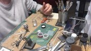
USS Voyager WIP Vid - 006 by Steve J, on Flickr
More pics...
Large secondary hull windows are masked off before painting the brass frames with Mister Surfacer thick primer:
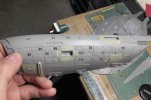
USS Voyager WIP Img - 085 by Steve J, on Flickr
Large window groups unmasked after brushing with Mister Surfacer. The curved structural support beams on deck 2 are also given a brush:
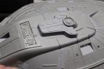
USS Voyager WIP Img - 086 by Steve J, on Flickr
Recessed deck 2 egress hatch is painted with Mister Surfacer after modifications were complete:
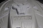
USS Voyager WIP Img - 087 by Steve J, on Flickr
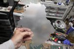
I found this sheet of .030 clear plastic sheet with its protective film still intact. I will use this to cut individual rectangular bits to fill in the smaller rectagular window openings in the hull. This will take some time to do but it should look great when I'm done:
USS Voyager WIP Img - 088 by Steve J, on Flickr
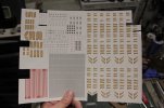
This is a sheet of extra decals meatloafr over on All Scale Trek printed for me when I was working on the Ent E. He included some sized to fit the Voyager too. Lots of good stuff to help with detailing a variety of kits:
USS Voyager WIP Img - 089 by Steve J, on Flickr
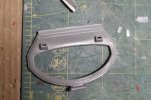
Secondary hull forward photorp launcher openings drilled out and filed to shape.
The openings will be filled with two tiny bits of clear styrene shown to the upper right:
USS Voyager WIP Img - 090 by Steve J, on Flickr
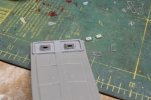
Spine photorp launchers opened up. Kit molded frames were sanded off and will be replaced with the thicker frames made from Evergreen strip shown to the right. Clear rectangular styrene bits will be inserted thru the new frames and out the back for lighting:
USS Voyager WIP Img - 091 by Steve J, on Flickr
The secondary hull is glued together. A strip of white Plasruct is glued into the lower secondary hull to reinforce the seam between the assembled hull halves:
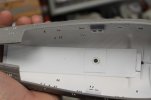
USS Voyager WIP Img - 092 by Steve J, on Flickr
Tube for lower power jack is installed into the secondary hull. I will need to sand and scrape the large seam that runs down the center of the hull.
I'll also need to remove some plastic for installing more photo-etch:
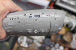
USS Voyager WIP Img - 093 by Steve J, on Flickr
Mixing up hull color "A" per the Revell instruction sheet. 70% light grey and 30% grey enamel:

USS Voyager WIP Vid - 006 by Steve J, on Flickr
More pics...
Large secondary hull windows are masked off before painting the brass frames with Mister Surfacer thick primer:

USS Voyager WIP Img - 085 by Steve J, on Flickr
Large window groups unmasked after brushing with Mister Surfacer. The curved structural support beams on deck 2 are also given a brush:

USS Voyager WIP Img - 086 by Steve J, on Flickr
Recessed deck 2 egress hatch is painted with Mister Surfacer after modifications were complete:

USS Voyager WIP Img - 087 by Steve J, on Flickr
I found this sheet of .030 clear plastic sheet with its protective film still intact. I will use this to cut individual rectangular bits to fill in the smaller rectagular window openings in the hull. This will take some time to do but it should look great when I'm done:

USS Voyager WIP Img - 088 by Steve J, on Flickr
This is a sheet of extra decals meatloafr over on All Scale Trek printed for me when I was working on the Ent E. He included some sized to fit the Voyager too. Lots of good stuff to help with detailing a variety of kits:

USS Voyager WIP Img - 089 by Steve J, on Flickr
Secondary hull forward photorp launcher openings drilled out and filed to shape.
The openings will be filled with two tiny bits of clear styrene shown to the upper right:

USS Voyager WIP Img - 090 by Steve J, on Flickr
Spine photorp launchers opened up. Kit molded frames were sanded off and will be replaced with the thicker frames made from Evergreen strip shown to the right. Clear rectangular styrene bits will be inserted thru the new frames and out the back for lighting:

USS Voyager WIP Img - 091 by Steve J, on Flickr
The secondary hull is glued together. A strip of white Plasruct is glued into the lower secondary hull to reinforce the seam between the assembled hull halves:

USS Voyager WIP Img - 092 by Steve J, on Flickr
Tube for lower power jack is installed into the secondary hull. I will need to sand and scrape the large seam that runs down the center of the hull.
I'll also need to remove some plastic for installing more photo-etch:

USS Voyager WIP Img - 093 by Steve J, on Flickr
trekriffic
Well-Known Member
- Joined
- Jan 6, 2012
- Messages
- 1,010
Size K DC coaxial power jack:
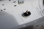
USS Voyager WIP Img - 094 by Steve J, on Flickr
Upper saucer brass window frames reinforced with AVES Apoxy Sculpt at the edges to prevent them from popping off if pressed on during the tape masking process when the hull gets its final coats:
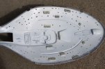
USS Voyager WIP Img - 095 by Steve J, on Flickr
Custom display stand components:
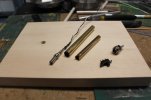
USS Voyager WIP Img - 096 by Steve J, on Flickr
The display tube is made up of two sections of brass tubing:
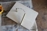
USS Voyager WIP Img - 097 by Steve J, on Flickr
Test fitting display tube to wooden base. The tube sports a size K coaxial power plug mating to the size K jack in the underside of the ship:
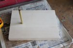
USS Voyager WIP Img - 098 by Steve J, on Flickr
Test fit of taped together model sitting level on the display stand:
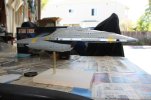
USS Voyager WIP Img - 099 by Steve J, on Flickr
Various photo-etch hatches and panels are glued onto the ventral surface of the secondary hull using slow cure CA.
This is some very nice added detail:
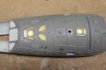
USS Voyager WIP Img - 100 by Steve J, on Flickr
I used this green pre-wired SMD LED to illuminate two fiber optic strands for the starboard nacelle upper and lower aft running lights.
A white plastic tube houses the LED and the ends of the strands that butt up against it:
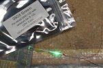
USS Voyager WIP Img - 101 by Steve J, on Flickr
Backside of a section of high density ultra narrow blue LED strip . I had to solder 30 AWG solid Kynar wire to the two grain-of-rice sized contacts on the end of the strip. Each contact is about 1 mm long by 0.5 mm wide. I didn't have any black Kynar so went with white for the positive and red for the negative leg:
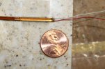
USS Voyager WIP Img - 102 by Steve J, on Flickr
This reminded me of one of those stick insects. The rarely seen, ultra thin, LED strip light insect - Exiguum Spoliare Lumen Insectum:
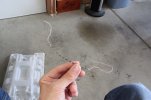
USS Voyager WIP Img - 103 by Steve J, on Flickr

USS Voyager WIP Img - 094 by Steve J, on Flickr
Upper saucer brass window frames reinforced with AVES Apoxy Sculpt at the edges to prevent them from popping off if pressed on during the tape masking process when the hull gets its final coats:

USS Voyager WIP Img - 095 by Steve J, on Flickr
Custom display stand components:

USS Voyager WIP Img - 096 by Steve J, on Flickr
The display tube is made up of two sections of brass tubing:

USS Voyager WIP Img - 097 by Steve J, on Flickr
Test fitting display tube to wooden base. The tube sports a size K coaxial power plug mating to the size K jack in the underside of the ship:

USS Voyager WIP Img - 098 by Steve J, on Flickr
Test fit of taped together model sitting level on the display stand:

USS Voyager WIP Img - 099 by Steve J, on Flickr
Various photo-etch hatches and panels are glued onto the ventral surface of the secondary hull using slow cure CA.
This is some very nice added detail:

USS Voyager WIP Img - 100 by Steve J, on Flickr
I used this green pre-wired SMD LED to illuminate two fiber optic strands for the starboard nacelle upper and lower aft running lights.
A white plastic tube houses the LED and the ends of the strands that butt up against it:

USS Voyager WIP Img - 101 by Steve J, on Flickr
Backside of a section of high density ultra narrow blue LED strip . I had to solder 30 AWG solid Kynar wire to the two grain-of-rice sized contacts on the end of the strip. Each contact is about 1 mm long by 0.5 mm wide. I didn't have any black Kynar so went with white for the positive and red for the negative leg:

USS Voyager WIP Img - 102 by Steve J, on Flickr
This reminded me of one of those stick insects. The rarely seen, ultra thin, LED strip light insect - Exiguum Spoliare Lumen Insectum:

USS Voyager WIP Img - 103 by Steve J, on Flickr
trekriffic
Well-Known Member
- Joined
- Jan 6, 2012
- Messages
- 1,010
The LED strip will be attached to the vertical face of a section of right angle plastic channel installed atop a section of 3 mm square tubing glued along the centerline of the lower nacelle half. A strip of adhesive backed aluminum foil can be seen stuck down to the horizontal face of the channel below where the LED strip will be located:
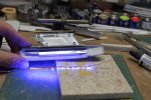
USS Voyager WIP Img - 104 by Steve J, on Flickr
Light test of green starboard nacelle formation light:
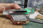
USS Voyager WIP Img - 105 by Steve J, on Flickr
Blue LED strip light test after gluing into nacelle:
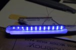
USS Voyager WIP Img - 106 by Steve J, on Flickr
Light test using LED strip without diffusion:
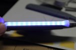
USS Voyager WIP Img - 107 by Steve J, on Flickr
I used thin styrofoam packing sheet folded over on itself six layers thick to eliminate any hot spots:
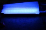
USS Voyager WIP Img - 108 by Steve J, on Flickr
Port nacelle red formation light tested:
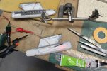
USS Voyager WIP Img - 110 by Steve J, on Flickr
I used a tiny pre-wired SMD LED (about the size of a flea) inside a piece of styrene tubing into which a short length of fiber optic strand was inserted. The strand takes a 90 degree turn before exiting the hull thru a small hole I had drilled previously. I bent the fiber over the tip of my soldering iron before it got too hot:
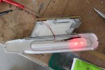
USS Voyager WIP Img - 111 by Steve J, on Flickr
Port nacelle lower red formation light. Lit by a fiber optic strand:
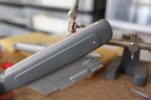
USS Voyager WIP Img - 112 by Steve J, on Flickr
Clear bussard inserts are glued in place after some modification. AVES Apoxy Sculpt was used to fill in any small gaps:
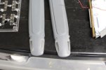
USS Voyager WIP Img - 113 by Steve J, on Flickr
Upper nacelle half after installation of the clear bussard parts. The inside surface was sanded with 600 grit paper to help diffuse the red light from the LEDs which will be installed in the lower half:
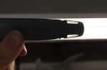
USS Voyager WIP Img - 114 by Steve J, on Flickr
That's all for now. Please forgive the massive photo blast; as you can see, I had some catching up to do with my posts.

USS Voyager WIP Img - 104 by Steve J, on Flickr
Light test of green starboard nacelle formation light:

USS Voyager WIP Img - 105 by Steve J, on Flickr
Blue LED strip light test after gluing into nacelle:

USS Voyager WIP Img - 106 by Steve J, on Flickr
Light test using LED strip without diffusion:

USS Voyager WIP Img - 107 by Steve J, on Flickr
I used thin styrofoam packing sheet folded over on itself six layers thick to eliminate any hot spots:

USS Voyager WIP Img - 108 by Steve J, on Flickr
Port nacelle red formation light tested:

USS Voyager WIP Img - 110 by Steve J, on Flickr
I used a tiny pre-wired SMD LED (about the size of a flea) inside a piece of styrene tubing into which a short length of fiber optic strand was inserted. The strand takes a 90 degree turn before exiting the hull thru a small hole I had drilled previously. I bent the fiber over the tip of my soldering iron before it got too hot:

USS Voyager WIP Img - 111 by Steve J, on Flickr
Port nacelle lower red formation light. Lit by a fiber optic strand:

USS Voyager WIP Img - 112 by Steve J, on Flickr
Clear bussard inserts are glued in place after some modification. AVES Apoxy Sculpt was used to fill in any small gaps:

USS Voyager WIP Img - 113 by Steve J, on Flickr
Upper nacelle half after installation of the clear bussard parts. The inside surface was sanded with 600 grit paper to help diffuse the red light from the LEDs which will be installed in the lower half:

USS Voyager WIP Img - 114 by Steve J, on Flickr
That's all for now. Please forgive the massive photo blast; as you can see, I had some catching up to do with my posts.
trekriffic
Well-Known Member
- Joined
- Jan 6, 2012
- Messages
- 1,010
Warping right along…
Decided to test out the backlit panel I installed in the top half of the fantail. I'm using a rectangular cool white ultrabright LED:
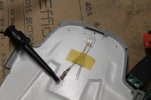
USS Voyager WIP Img - 116 by Steve J, on Flickr
I glued a rectangular section of .010 thick clear styrene behind the brass window frames in the upper half of the fantail parts. Then I trimmed the margins of the backlit panel to fit behind the clear plastic windows and pressed it snugly into place.
The window frames will be retouched later on with more of the light grey hull color:
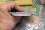
USS Voyager WIP Img - 117 by Steve J, on Flickr
Held upside down but shows off the fantail windows with backlit panel lit up. Overexposed a tad in this photo; it looks better in person:
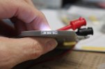
USS Voyager WIP Img - 118 by Steve J, on Flickr
Pursuing the wiring theme…
First nacelle light test with bussard LEDs tied into the blue LED strip circuit:
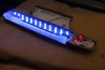
USS Voyager WIP Img - 118 by Steve J, on Flickr
Forward bussard red LEDs with 470 ohm resistors are soldered in a parallel circuit from wires soldered to contacts on the end of the blue LED strip. Devcon Weld-it household adhesive has insulating properties so I will spread it all over the legs of the LEDs as well as the wires and solder joints once the glue dries I will cover the wiring up with a thin piece of aluminum mylar for better light reflectance:
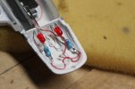
USS Voyager WIP Img - 119 by Steve J, on Flickr
Light test. Note a diffusion panel made from a folded tube of styrofoam packing sheet between the clear warp grills and the blue LED strip and mylar foil in the nose under the red LED lights:
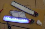
USS Voyager WIP Img - 120 by Steve J, on Flickr
Wires from the blue LED strip and green formation light LED are paired and soldered together before being soldered to the positive and negative power leads:
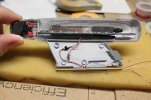
USS Voyager WIP Img - 121 by Steve J, on Flickr
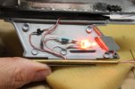
A single 2mm amber LED provides illumination to both the forward intake (not shown because it's on the upper half of the wing) and both upper and lower halves of the rear exhaust vents. Blobs of Devcon Weld-It Adhesive hold the wiring in place and serve to insulate any solder joints due to its insulating properties:
USS Voyager WIP Img - 124 by Steve J, on Flickr
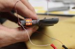
Impulse engine exhaust vents after glue up. A diffuser panel behind the vents filters light from a single 2mm amber LED:
USS Voyager WIP Img - 125 by Steve J, on Flickr
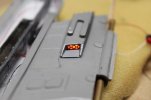
Impulse engine intake vent lit with an amber 2mm LED. A diffuser panel made by sanding a small rectangle of .010 clear styrene sits up against the back of the photo-etch brass screen:
USS Voyager WIP Img - 126 by Steve J, on Flickr
Next up… light tests of the completed starboard nacelle.
Decided to test out the backlit panel I installed in the top half of the fantail. I'm using a rectangular cool white ultrabright LED:

USS Voyager WIP Img - 116 by Steve J, on Flickr
I glued a rectangular section of .010 thick clear styrene behind the brass window frames in the upper half of the fantail parts. Then I trimmed the margins of the backlit panel to fit behind the clear plastic windows and pressed it snugly into place.
The window frames will be retouched later on with more of the light grey hull color:

USS Voyager WIP Img - 117 by Steve J, on Flickr
Held upside down but shows off the fantail windows with backlit panel lit up. Overexposed a tad in this photo; it looks better in person:

USS Voyager WIP Img - 118 by Steve J, on Flickr
Pursuing the wiring theme…
First nacelle light test with bussard LEDs tied into the blue LED strip circuit:

USS Voyager WIP Img - 118 by Steve J, on Flickr
Forward bussard red LEDs with 470 ohm resistors are soldered in a parallel circuit from wires soldered to contacts on the end of the blue LED strip. Devcon Weld-it household adhesive has insulating properties so I will spread it all over the legs of the LEDs as well as the wires and solder joints once the glue dries I will cover the wiring up with a thin piece of aluminum mylar for better light reflectance:

USS Voyager WIP Img - 119 by Steve J, on Flickr
Light test. Note a diffusion panel made from a folded tube of styrofoam packing sheet between the clear warp grills and the blue LED strip and mylar foil in the nose under the red LED lights:

USS Voyager WIP Img - 120 by Steve J, on Flickr
Wires from the blue LED strip and green formation light LED are paired and soldered together before being soldered to the positive and negative power leads:

USS Voyager WIP Img - 121 by Steve J, on Flickr
A single 2mm amber LED provides illumination to both the forward intake (not shown because it's on the upper half of the wing) and both upper and lower halves of the rear exhaust vents. Blobs of Devcon Weld-It Adhesive hold the wiring in place and serve to insulate any solder joints due to its insulating properties:

USS Voyager WIP Img - 124 by Steve J, on Flickr
Impulse engine exhaust vents after glue up. A diffuser panel behind the vents filters light from a single 2mm amber LED:

USS Voyager WIP Img - 125 by Steve J, on Flickr
Impulse engine intake vent lit with an amber 2mm LED. A diffuser panel made by sanding a small rectangle of .010 clear styrene sits up against the back of the photo-etch brass screen:

USS Voyager WIP Img - 126 by Steve J, on Flickr
Next up… light tests of the completed starboard nacelle.
Pantherman
Well-Known Member
- Joined
- Feb 10, 2022
- Messages
- 3,691
That's some serious building. Out of this world. PanthermanWarping right along…
Decided to test out the backlit panel I installed in the top half of the fantail. I'm using a rectangular cool white ultrabright LED:
View attachment 101418
USS Voyager WIP Img - 116 by Steve J, on Flickr
I glued a rectangular section of .010 thick clear styrene behind the brass window frames in the upper half of the fantail parts. Then I trimmed the margins of the backlit panel to fit behind the clear plastic windows and pressed it snugly into place.
The window frames will be retouched later on with more of the light grey hull color:
View attachment 101419
USS Voyager WIP Img - 117 by Steve J, on Flickr
Held upside down but shows off the fantail windows with backlit panel lit up. Overexposed a tad in this photo; it looks better in person:
View attachment 101420
USS Voyager WIP Img - 118 by Steve J, on Flickr
Pursuing the wiring theme…
First nacelle light test with bussard LEDs tied into the blue LED strip circuit:
View attachment 101421
USS Voyager WIP Img - 118 by Steve J, on Flickr
Forward bussard red LEDs with 470 ohm resistors are soldered in a parallel circuit from wires soldered to contacts on the end of the blue LED strip. Devcon Weld-it household adhesive has insulating properties so I will spread it all over the legs of the LEDs as well as the wires and solder joints once the glue dries I will cover the wiring up with a thin piece of aluminum mylar for better light reflectance:
View attachment 101422
USS Voyager WIP Img - 119 by Steve J, on Flickr
Light test. Note a diffusion panel made from a folded tube of styrofoam packing sheet between the clear warp grills and the blue LED strip and mylar foil in the nose under the red LED lights:
View attachment 101423
USS Voyager WIP Img - 120 by Steve J, on Flickr
Wires from the blue LED strip and green formation light LED are paired and soldered together before being soldered to the positive and negative power leads:
View attachment 101424
USS Voyager WIP Img - 121 by Steve J, on Flickr
A single 2mm amber LED provides illumination to both the forward intake (not shown because it's on the upper half of the wing) and both upper and lower halves of the rear exhaust vents. Blobs of Devcon Weld-It Adhesive hold the wiring in place and serve to insulate any solder joints due to its insulating properties:
View attachment 101425
USS Voyager WIP Img - 124 by Steve J, on Flickr
Impulse engine exhaust vents after glue up. A diffuser panel behind the vents filters light from a single 2mm amber LED:
View attachment 101426
USS Voyager WIP Img - 125 by Steve J, on Flickr
Impulse engine intake vent lit with an amber 2mm LED. A diffuser panel made by sanding a small rectangle of .010 clear styrene sits up against the back of the photo-etch brass screen:
View attachment 101427
USS Voyager WIP Img - 126 by Steve J, on Flickr
Next up… light tests of the completed starboard nacelle.
Down Time
Well-Known Member
- Joined
- Dec 17, 2022
- Messages
- 1,655
Yeah, well, sort of is.....That's some serious building. Out of this world. Pantherman
Trekriffic, keep going truly is on a whole different level and as Pantherman said, out of this world build!!!
trekriffic
Well-Known Member
- Joined
- Jan 6, 2012
- Messages
- 1,010
Thanks guys!
More nacelle light test images...
Nacelle and winglet halves are glued together using Testors red tube glue;
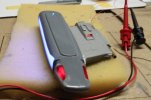
USS Voyager WIP Img - 127 by Steve J, on Flickr
Amber Impulse engine and green starboard formation light aglow. Will need some filler putty and light sanding before primer and finish paint coats:
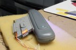
USS Voyager WIP Img - 128 by Steve J, on Flickr
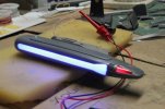
USS Voyager WIP Img - 129 by Steve J, on Flickr
Lit bussard detail. I used the same material to diffuse the light from the warp grills and the bussards. This looks even better to the naked eye:
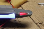
USS Voyager WIP Img - 130 by Steve J, on Flickr
That's it for now. I added some additional detail to the aft ends of the nacelles using half round Evergreen rod.
I also added a tiny round piece of tubing to the slot in that U shaped thing atop the impulse engines.
Pictures to follow shortly once I download them to my laptop.
More nacelle light test images...
Nacelle and winglet halves are glued together using Testors red tube glue;

USS Voyager WIP Img - 127 by Steve J, on Flickr
Amber Impulse engine and green starboard formation light aglow. Will need some filler putty and light sanding before primer and finish paint coats:

USS Voyager WIP Img - 128 by Steve J, on Flickr

USS Voyager WIP Img - 129 by Steve J, on Flickr
Lit bussard detail. I used the same material to diffuse the light from the warp grills and the bussards. This looks even better to the naked eye:

USS Voyager WIP Img - 130 by Steve J, on Flickr
That's it for now. I added some additional detail to the aft ends of the nacelles using half round Evergreen rod.
I also added a tiny round piece of tubing to the slot in that U shaped thing atop the impulse engines.
Pictures to follow shortly once I download them to my laptop.
trekriffic
Well-Known Member
- Joined
- Jan 6, 2012
- Messages
- 1,010
Thanks Q. Glad you like it!Definitely enjoying your progress on this
Here's the photo bomb for today...
Ribbed detailing was added to the aft ends of the nacelles. I used half round Evergreen rod attached with CA glue:
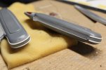
USS Voyager WIP Img - 131 by Steve J, on Flickr
A small slice of round Evergreen rod is glued into the slot of the horseshoe atop each impulse engine.
Afterward I filled it with AVES putty leaving a slight indent on top. A tiny detail to be sure:
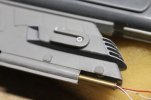
USS Voyager WIP Img - 132 by Steve J, on Flickr
Masked off the raised rib detail on the clear part behind the main deflector at the front of the secondary hull using Tamiya tape sliced very thin:
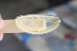
USS Voyager WIP Img - 133 by Steve J, on Flickr
Liquid mask was applied to the center section which is semigloss white according to the instructions.
Then I painted the ribs with a mix of rust brown and orange enamels:
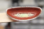
USS Voyager WIP Img - 134 by Steve J, on Flickr
I added some more International Orange to the mix for the second coat of the deflector grill ribs:
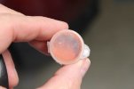
USS Voyager WIP Img - 135 by Steve J, on Flickr
Wiring up lower half of the fantail with the red and green formation lights and the clear flashing nav light in the center.
The nav light will be wired to a Tenacontrols flasher board in either the secondary or primary hull, haven't decided that yet.
The formation lights don't flash and will be wired to a separate power circuit:
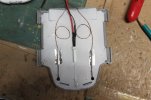
USS Voyager WIP Img - 136 by Steve J, on Flickr
The upper half of the fantail was wired with a rectangular clear LED and light blocked on the top and sides using mylar foil.
I also glued a tiny rare earth magnet between the legs of the LED:
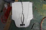
USS Voyager WIP Img - 137 by Steve J, on Flickr
Nacelle wires were paired together - one positive and one negative pair from each nacelle soldered together.
These were then soldered to a single positive and negative feeder wire for each pair.
Shrink tubing was then shrunk down over the solder joints:
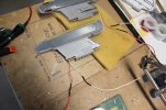
USS Voyager WIP Img - 138 by Steve J, on Flickr
Took a break from wiring and sprayed the secondary hull with grey primer.
I sprayed the photo-etch brass hatches and covers with adhesion promoter though before the grey primer.
The nasty seam down the middle was a bitch to fill and sand but I think it looks pretty good now:
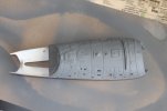
USS Voyager WIP Img - 139 by Steve J, on Flickr
I also sprayed the top of the saucer hull with grey primer:
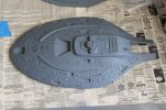
USS Voyager WIP Img - 140 by Steve J, on Flickr
Next I'll start gluing .010 styrene plastic to the backs of the window frames of the larger window groups before attaching the backlit interior room panels that will be lit from behind, I have a roll of "natural white" LED strip I can use for this so they will light up nicely.
Pantherman
Well-Known Member
- Joined
- Feb 10, 2022
- Messages
- 3,691
That's some impressive work. I like it. Can't wait to see the next installment. PanthermanThanks Q. Glad you like it!
Here's the photo bomb for today...
Ribbed detailing was added to the aft ends of the nacelles. I used half round Evergreen rod attached with CA glue:
View attachment 101632
USS Voyager WIP Img - 131 by Steve J, on Flickr
A small slice of round Evergreen rod is glued into the slot of the horseshoe atop each impulse engine.
Afterward I filled it with AVES putty leaving a slight indent on top. A tiny detail to be sure:
View attachment 101633
USS Voyager WIP Img - 132 by Steve J, on Flickr
Masked off the raised rib detail on the clear part behind the main deflector at the front of the secondary hull using Tamiya tape sliced very thin:
View attachment 101634
USS Voyager WIP Img - 133 by Steve J, on Flickr
Liquid mask was applied to the center section which is semigloss white according to the instructions.
Then I painted the ribs with a mix of rust brown and orange enamels:
View attachment 101635
USS Voyager WIP Img - 134 by Steve J, on Flickr
I added some more International Orange to the mix for the second coat of the deflector grill ribs:
View attachment 101636
USS Voyager WIP Img - 135 by Steve J, on Flickr
Wiring up lower half of the fantail with the red and green formation lights and the clear flashing nav light in the center.
The nav light will be wired to a Tenacontrols flasher board in either the secondary or primary hull, haven't decided that yet.
The formation lights don't flash and will be wired to a separate power circuit:
View attachment 101637
USS Voyager WIP Img - 136 by Steve J, on Flickr
The upper half of the fantail was wired with a rectangular clear LED and light blocked on the top and sides using mylar foil.
I also glued a tiny rare earth magnet between the legs of the LED:
View attachment 101638
USS Voyager WIP Img - 137 by Steve J, on Flickr
Nacelle wires were paired together - one positive and one negative pair from each nacelle soldered together.
These were then soldered to a single positive and negative feeder wire for each pair.
Shrink tubing was then shrunk down over the solder joints:
View attachment 101639
USS Voyager WIP Img - 138 by Steve J, on Flickr
Took a break from wiring and sprayed the secondary hull with grey primer.
I sprayed the photo-etch brass hatches and covers with adhesion promoter though before the grey primer.
The nasty seam down the middle was a bitch to fill and sand but I think it looks pretty good now:
View attachment 101640
USS Voyager WIP Img - 139 by Steve J, on Flickr
I also sprayed the top of the saucer hull with grey primer:
View attachment 101641
USS Voyager WIP Img - 140 by Steve J, on Flickr
Next I'll start gluing .010 styrene plastic to the backs of the window frames of the larger window groups before attaching the backlit interior room panels that will be lit from behind, I have a roll of "natural white" LED strip I can use for this so they will light up nicely.
trekriffic
Well-Known Member
- Joined
- Jan 6, 2012
- Messages
- 1,010
Just got these in the mail from Shapeways…
Voyager Shuttle Bay Interior Replacement
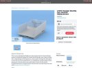
USS Voyager WIP Img - 141 by Steve J, on Flickr
Voyager Shuttlecraft Pack
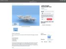
USS Voyager WIP Img - 142 by Steve J, on Flickr
Both kits are molded in clear ultra fine detail plastic suitable for lighting.
The type 8 and 9 shuttles are hollow with internal cockpit seats and rear walls.
Hard to believe based on the wee size of these tiny ships.
Good thing I have some clear white flea sized SMD LED's from HDA Modelworx.
Hopefully meatloafr over on AST can help me with decals as Shapeways doesn't provide any.
Oh yeah… this is gonna be fun!
Voyager Shuttle Bay Interior Replacement

USS Voyager WIP Img - 141 by Steve J, on Flickr
Voyager Shuttlecraft Pack

USS Voyager WIP Img - 142 by Steve J, on Flickr
Both kits are molded in clear ultra fine detail plastic suitable for lighting.
The type 8 and 9 shuttles are hollow with internal cockpit seats and rear walls.
Hard to believe based on the wee size of these tiny ships.
Good thing I have some clear white flea sized SMD LED's from HDA Modelworx.
Hopefully meatloafr over on AST can help me with decals as Shapeways doesn't provide any.
Oh yeah… this is gonna be fun!
Last edited:
trekriffic
Well-Known Member
- Joined
- Jan 6, 2012
- Messages
- 1,010
Some assembly required…
LED tubes and fibers painted black for light blocking close but not inside the tubes to block any stray light from either
the flasher or the window rectangular LED which are all painted black on the outside and covered with foil for good measure.
All wiring is finished for fantail LEDs:
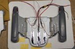
USS Voyager WIP Img - 143 by Steve J, on Flickr
Clamping after gluing with Testors red tube glue.
Feeding the fiber on the aft top was a lot of fun but eventually they went thru.
I made sure they were extra long in case I broke the end during the press the halves together step.
I used a good amount of the old red tube styrene cement though so hope to see a lot of liquid plastic
squeezed out of the seams- then I know I have a solidly welded joint:
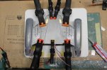
USS Voyager WIP Img - 144 by Steve J, on Flickr
I extended the aft of the fan tail around the window:
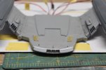
USS Voyager WIP Img - 146 by Steve J, on Flickr
Light test. I added a 1/16" piece of strip to the top edge over the window to approx the same level as the window pillars.
Will feather into the hull using AVES before more filing and sanding:
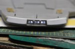
USS Voyager WIP Img - 147 by Steve J, on Flickr
Do you see what I see?
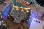
USS Voyager WIP Img - 148 by Steve J, on Flickr
LED tubes and fibers painted black for light blocking close but not inside the tubes to block any stray light from either
the flasher or the window rectangular LED which are all painted black on the outside and covered with foil for good measure.
All wiring is finished for fantail LEDs:

USS Voyager WIP Img - 143 by Steve J, on Flickr
Clamping after gluing with Testors red tube glue.
Feeding the fiber on the aft top was a lot of fun but eventually they went thru.
I made sure they were extra long in case I broke the end during the press the halves together step.
I used a good amount of the old red tube styrene cement though so hope to see a lot of liquid plastic
squeezed out of the seams- then I know I have a solidly welded joint:

USS Voyager WIP Img - 144 by Steve J, on Flickr
I extended the aft of the fan tail around the window:

USS Voyager WIP Img - 146 by Steve J, on Flickr
Light test. I added a 1/16" piece of strip to the top edge over the window to approx the same level as the window pillars.
Will feather into the hull using AVES before more filing and sanding:

USS Voyager WIP Img - 147 by Steve J, on Flickr
Do you see what I see?

USS Voyager WIP Img - 148 by Steve J, on Flickr
trekriffic
Well-Known Member
- Joined
- Jan 6, 2012
- Messages
- 1,010
Read on…
OOPS!
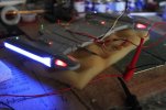
USS Voyager WIP Img - 149 by Steve J, on Flickr
Bad light leak due to an oversite on my part on both of the aft hinges on the winglets and, to a lesser extent, the forward wing face to the forward round hinge of the hull. Will have to fix:
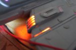
USS Voyager WIP Img - 150 by Steve J, on Flickr
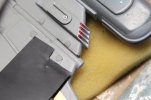
Fixing the godzillas of light leaks. Thin black styrene sheet.
I literally uise very little of this stuff but it was just perfect for gluing onto the winglet sides of the fore and aft hinge segments. Still, you can see a small gap where i didn't get the shim quite far enough into the gap. i will cut a small wedge piece tomorrow to fill the tiny gaps ( top and bottom aft) left from the first attempt with a little cement of the winglet side of the hinge joint:
USS Voyager WIP Img - 151 by Steve J, on Flickr
Slipping a piece of Testors coarse black sanding film into the gap and working it up and down about 8 times to widen the gap between the winglet and the fantail hinge segments before shoving a piece of black styrene sheet into the gap to cover the light leak caused by the impulse engine 2 mm amber LED:
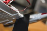
USS Voyager WIP Img - 152 by Steve J, on Flickr
Had to reglue the port forward hinge cover after it split open while I figured out how to fix the light leaks. These covers can be trouble to keep from splitting when the engines are raised and lowered:
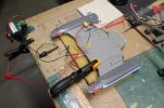
USS Voyager WIP Img - 153 by Steve J, on Flickr
NEXT UP…
More light tests and uber detailing. The major light leaks along the hinges are a thing of the past now.
Also, my re-glued hinge cover is holding but I came up with a simple idea for preventing any future cover cracks or splits.
OOPS!

USS Voyager WIP Img - 149 by Steve J, on Flickr
Bad light leak due to an oversite on my part on both of the aft hinges on the winglets and, to a lesser extent, the forward wing face to the forward round hinge of the hull. Will have to fix:

USS Voyager WIP Img - 150 by Steve J, on Flickr
Fixing the godzillas of light leaks. Thin black styrene sheet.
I literally uise very little of this stuff but it was just perfect for gluing onto the winglet sides of the fore and aft hinge segments. Still, you can see a small gap where i didn't get the shim quite far enough into the gap. i will cut a small wedge piece tomorrow to fill the tiny gaps ( top and bottom aft) left from the first attempt with a little cement of the winglet side of the hinge joint:

USS Voyager WIP Img - 151 by Steve J, on Flickr
Slipping a piece of Testors coarse black sanding film into the gap and working it up and down about 8 times to widen the gap between the winglet and the fantail hinge segments before shoving a piece of black styrene sheet into the gap to cover the light leak caused by the impulse engine 2 mm amber LED:

USS Voyager WIP Img - 152 by Steve J, on Flickr
Had to reglue the port forward hinge cover after it split open while I figured out how to fix the light leaks. These covers can be trouble to keep from splitting when the engines are raised and lowered:

USS Voyager WIP Img - 153 by Steve J, on Flickr
NEXT UP…
More light tests and uber detailing. The major light leaks along the hinges are a thing of the past now.
Also, my re-glued hinge cover is holding but I came up with a simple idea for preventing any future cover cracks or splits.
trekriffic
Well-Known Member
- Joined
- Jan 6, 2012
- Messages
- 1,010
Clamping. Light test with consolidated wiring bundles:
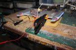
USS Voyager WIP Img - 154 by Steve J, on Flickr
I love a good clamp and this small ratchet clamp gives a good clamping for sure.
I'm thinking of punching out some small styrene discs to glue onto the four hinge covers.
That should do the trick if necessary. Hopefully I see some plastic squeezing from the seam in the morning:
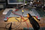
USS Voyager WIP Img - 155 by Steve J, on Flickr
Aft window LED light test:
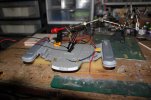
USS Voyager WIP Img - 156 by Steve J, on Flickr
Fantail windows with backlit panel.
This is after AVES application so all gaps have been filled, filed, and sanded.
Still some work to do on the top rim with the fantail deck above.
Then will brush with Mister Surfacer and sand some more:
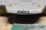
USS Voyager WIP Img - 157 by Steve J, on Flickr
All lights except the center white flasher are on:
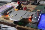
USS Voyager WIP Img - 158 by Steve J, on Flickr
I punched four discs out of thin Plastruct strip and glued them to the ends of each hinge using CA.
This should prevent any further stress cracking of the hinge cylinders caused by the engagement of the hinge mechanism:
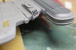
USS Voyager WIP Img - 161 by Steve J, on Flickr
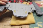
USS Voyager WIP Img - 162 by Steve J, on Flickr
Small half round rod segments 2 mm long are added to the raised panels flanking the forward hinge cover caps:
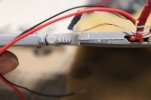
USS Voyager WIP Img - 163 by Steve J, on Flickr
Mister Surfacer is brushed around the aft end of the fantail after putty has cured:
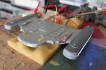
USS Voyager WIP Img - 165 by Steve J, on Flickr
Aerowing 3D printed in clear ultra smooth material by Shapeways. Top view:
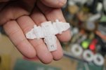
USS Voyager WIP Img - 167 by Steve J, on Flickr

USS Voyager WIP Img - 154 by Steve J, on Flickr
I love a good clamp and this small ratchet clamp gives a good clamping for sure.
I'm thinking of punching out some small styrene discs to glue onto the four hinge covers.
That should do the trick if necessary. Hopefully I see some plastic squeezing from the seam in the morning:

USS Voyager WIP Img - 155 by Steve J, on Flickr
Aft window LED light test:

USS Voyager WIP Img - 156 by Steve J, on Flickr
Fantail windows with backlit panel.
This is after AVES application so all gaps have been filled, filed, and sanded.
Still some work to do on the top rim with the fantail deck above.
Then will brush with Mister Surfacer and sand some more:

USS Voyager WIP Img - 157 by Steve J, on Flickr
All lights except the center white flasher are on:

USS Voyager WIP Img - 158 by Steve J, on Flickr
I punched four discs out of thin Plastruct strip and glued them to the ends of each hinge using CA.
This should prevent any further stress cracking of the hinge cylinders caused by the engagement of the hinge mechanism:

USS Voyager WIP Img - 161 by Steve J, on Flickr

USS Voyager WIP Img - 162 by Steve J, on Flickr
Small half round rod segments 2 mm long are added to the raised panels flanking the forward hinge cover caps:

USS Voyager WIP Img - 163 by Steve J, on Flickr
Mister Surfacer is brushed around the aft end of the fantail after putty has cured:

USS Voyager WIP Img - 165 by Steve J, on Flickr
Aerowing 3D printed in clear ultra smooth material by Shapeways. Top view:

USS Voyager WIP Img - 167 by Steve J, on Flickr
trekriffic
Well-Known Member
- Joined
- Jan 6, 2012
- Messages
- 1,010
I thought about it, even took screenshots of the 1/1000 scale bay on Shapeways but… I dunno. Removing the kit shuttle from the underside of the saucer would be a real challenge and I've already spent so much time n this build, I'm thinking now about trying to light it and display it on its own brass display tube on the stand.You have a plan for the Aeroshuttle bay?
trekriffic
Well-Known Member
- Joined
- Jan 6, 2012
- Messages
- 1,010
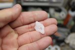
Delta Flier printed by Shapeways. This tiny ship is hollow:
USS Voyager WIP Img - 169 by Steve J, on Flickr
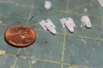
Types 8 and 9 shuttle craft included in the Voyager shuttle craft pack by Shapeways.
I lost one of the type 8: shuttles down the washtub drain while cleaning the parts.
These tiny shuttles are amazingly detailed with cockpits and pilot seats visible thru the forward windows:
USS Voyager WIP Img - 170 by Steve J, on Flickr
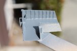
I purchased a printed 1/670 scale accurate shuttle bay for my Revell Voyager.
After adding sections of Evergreen sheet to the backs of the exceptionally thin floor and walls I sprayed the bay with Krylon Colormaxx grey primer:
USS Voyager WIP Img - 171 by Steve J, on Flickr
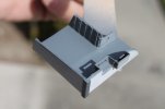
Adding Evergreen and Plastruct strip to the backside of the thin, fragile walls and floor along with angle brackets to reinforce the corners really strengthened the shuttle bay. This photo is after two coats of primer:
USS Voyager WIP Img - 172 by Steve J, on Flickr
.010 styrene sheet was trimmed to fit under the alarmingly thin rear section of the floor and to stiffen the equally fragile walls of the shuttle bay:
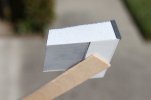
USS Voyager WIP Img - 173 by Steve J, on Flickr
Evergreen sheet trimmed to fit and glued to the back of the rear wall of the bay:
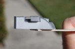
USS Voyager WIP Img - 174 by Steve J, on Flickr
Reinforcing the starboard side wall with Plastruct strip was a no brainer after it cracked off from the floor when I tried to straighten it.
The trick to doing this turned out to be heat. Prior to priming I soaked the parts in warm, soapy water to remove some wax residue;
this made the parts much more pliable and receptive to bending into alignment.
Lesson learned:
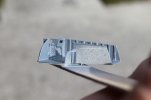
USS Voyager WIP Img - 175 by Steve J, on Flickr
Primed the shuttle bay roof panel, I'll add an LED strip down the center for lighting.
This part fits perfectly atop the shuttle bay walls during test fitting:
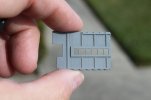
USS Voyager WIP Img - 176 by Steve J, on Flickr
Evergreen styrene strips were cut, glued, and filed to shape to give the window framing even thickness and a flat profile. AVES will be applied to match the silhouette of the framing and blend the thickened top rim into the rim of the fantail. The result will be a flat, vertical rim with a deeply recessed group of window.:
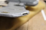
USS Voyager WIP Img - 177 by Steve J, on Flickr
Much improved fantail window framing:
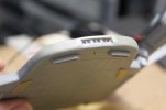
USS Voyager WIP Img - 178 by Steve J, on Flickr
More to come as I work on the deflector dish...

USS Voyager WIP Img - 169 by Steve J, on Flickr
Types 8 and 9 shuttle craft included in the Voyager shuttle craft pack by Shapeways.
I lost one of the type 8: shuttles down the washtub drain while cleaning the parts.
These tiny shuttles are amazingly detailed with cockpits and pilot seats visible thru the forward windows:

USS Voyager WIP Img - 170 by Steve J, on Flickr
I purchased a printed 1/670 scale accurate shuttle bay for my Revell Voyager.
After adding sections of Evergreen sheet to the backs of the exceptionally thin floor and walls I sprayed the bay with Krylon Colormaxx grey primer:

USS Voyager WIP Img - 171 by Steve J, on Flickr
Adding Evergreen and Plastruct strip to the backside of the thin, fragile walls and floor along with angle brackets to reinforce the corners really strengthened the shuttle bay. This photo is after two coats of primer:

USS Voyager WIP Img - 172 by Steve J, on Flickr
.010 styrene sheet was trimmed to fit under the alarmingly thin rear section of the floor and to stiffen the equally fragile walls of the shuttle bay:

USS Voyager WIP Img - 173 by Steve J, on Flickr
Evergreen sheet trimmed to fit and glued to the back of the rear wall of the bay:

USS Voyager WIP Img - 174 by Steve J, on Flickr
Reinforcing the starboard side wall with Plastruct strip was a no brainer after it cracked off from the floor when I tried to straighten it.
The trick to doing this turned out to be heat. Prior to priming I soaked the parts in warm, soapy water to remove some wax residue;
this made the parts much more pliable and receptive to bending into alignment.
Lesson learned:

USS Voyager WIP Img - 175 by Steve J, on Flickr
Primed the shuttle bay roof panel, I'll add an LED strip down the center for lighting.
This part fits perfectly atop the shuttle bay walls during test fitting:

USS Voyager WIP Img - 176 by Steve J, on Flickr
Evergreen styrene strips were cut, glued, and filed to shape to give the window framing even thickness and a flat profile. AVES will be applied to match the silhouette of the framing and blend the thickened top rim into the rim of the fantail. The result will be a flat, vertical rim with a deeply recessed group of window.:

USS Voyager WIP Img - 177 by Steve J, on Flickr
Much improved fantail window framing:

USS Voyager WIP Img - 178 by Steve J, on Flickr
More to come as I work on the deflector dish...
Similar threads
- Replies
- 10
- Views
- 3K
Latest posts
-
-
-
-
-
GREEN HORNET's BLACK BEAUTY MODEL KIT, 2021! $25.00 OBO! Sealed and Mint!!
- Latest: SuperheroSanctum
-
-
-
