The Ships of Firadis Pt 1.
- Thread starter Primen
- Start date
torgg said:I have the same art book from when I was a kid! I'll have to see if I can find it.
Mine's called 'Space Wars.' The text is mostly drivel, but the pics are an amazing cross-section of classic SF art. My buddy had one when I was a kid. I didn't find one until recently.
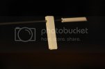
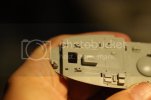
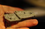
This is a flight deck from a 1/72nd scale B-29 kit I picked up a while back and decided to cannibalize. It has both an interesting shape and interesting detail, but more to the point, the combination of both deck and bulkheads makes it both light and strong. I had the intuition to use this as a connection point between the top and bottom parts of the dorsal boom. A platform suspended on the boom might add interest to the structure.
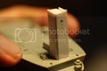
Creating mounting posts for the final boom. These will be faced later with appropriate detail.
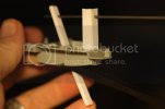
Here and in the next photo you can see two dark strips. These are carbon fiber control rods used for RC aircraft. They are very light and very strong. I saw them at the LHS and, on a whim decided to try them out, as my steel rods had a tendency to bow, ever so slightly. Pairing the rods and putting them in the vertical plane worked very well indeed. I had a long double boom with absolutely no bowing at all. However, they were very hard on my drill bits. I wore out three drill bits drilling four holes in two booms!
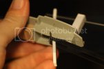
You can see a bit of steel rod poking through the end of the CF rods. By chance there was a nice notch in the side bulkheads of the B-29 wheel-well. By inserting the steel 'axle-pin' into that notch and then bracing the pin behind the 2nd mounting post I was able to create a tension that helped keep the lower boom in place for structure tests.
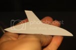
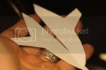
To symmetrically duplicate the magnetic base of the boom I taped two bits of sheet styrene together with double sided tape and roughed out the shape I wanted. I created 'wings' on either side to create additional grip for holding the boom for a sideways mount. This was the big test. I was very much hoping my little molybdenum magnets would hold the boom in place with the full weight of the dorsal tower pulling on it. If not, I would have to create a fixed boom tower for the model, greatly limiting options for different configurations and modularity.
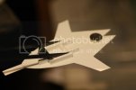
1st Magnet superglued in place. The big question was: how powerful would the magnet hold to the steel plate of my 'test cylinder' through one sheet of cardboard and two sheets of styrene? Would it hold the full weight of the tower? You can see here the structure for joining the CF rods to the styrene base. Heavy rod styrene was glued to the now joined halves of the base. A steel pin ran through the tube connecting the two mounts. Behind the CF rods is a bit of steel plate which sets the angle of the boom, and thus, the entire structure. This was carefully considered and then glued into place with CA, but in the event, a lot of adjusting went into it afterwards.
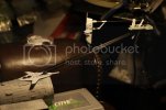
Success!
Even with only two magnets, the boom held firm to the test cylinder. For the first time I felt like I was beginning to see something that looked like the dredges that had wandered through my imagination all these years.
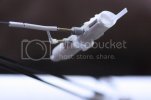
The following day.
I decided to add a third magnetic attachment point to the spotting top in order to have the option to raise it higher should it need more clearance from the boom beneath. The final angle of the boom would depend very much on how the shape and set of the tower combined with the overall length and shape of the hull. In my few efforts at cobbling together a scratch-build or kit-bashed spaceship, I found that often what killed the build was not lack of parts or incompatibility of materials, but slight discrepancies in size between two components. Many times I had the experience of finding two pieces from disparate sources that looked as though they ought to go together beautifully, but when finally joined, just didn't quite work. I was determined this time not to make that mistake: TEST EVERYTHING!!!
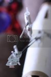
Here the platform comes into focus. The structure below is the '1st Cardboard Tube attempt' to which I now had superglued a strip of steel for the magnets to adhere to. Would the CA hold? In the event, it held beautifully. The wing magnets bent the thin styrene plate symmetrically and followed the contour of the cylinder, increasing the grip of the base and blending it to be conformal with the curve of the hull. This will have to be detailed carefully so that it retains flexibility.
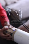
Carbon Fiber strips working very nicely without any hint of bowing. In Firadis, the dredges are described as using advanced 'powered matter' (nano-tech) throughout their structure, so it was nice to use something just a little bit high tech to achieve a solution with the build. ;D
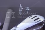
Moment of Truth! Steel strips CA'd to the actual dredge hull. No more Tests! Everything works! Hooraay!!!
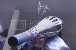
Note the steel pin wedged beneath the lower boom rods. This was the angle necessary to make the 'mid-boom platform/ (??) level. At this point I was just extatic that it all held together.
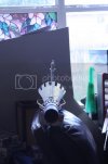
Head-on view, test for symmetry. Something I had never drawn.
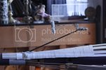
Profile shot of the dorsal boom tower. Note in the background (very blurry) is my Zvezda Varyag, 99% complete and almost fully rigged. Tried to finish it in time for the local contest this week, but work and my wife's pregnancy (almost went into labor Friday) nixed the effort.
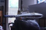
Near profile. At this point it was clear that the boom tower stood waaaaay too high over the hull. This would require adjusting both the base (easy) and the boom platform (tricky.)
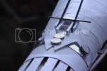
Close-up of the boom tower base. Note how the molybdenum magnets distort the thin styrene of the base to conform to the shape of the steel strip glued to the hull beneath.
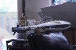
Mock-up. Tower is lowered now, seems to be working better with the hull. In addition I have roughed out the forward Navigation Island with a ping-pong ball glued to a flashlight head. I always imagined the Navigation Island would feature a spherical or ellipsoid structure to convey the idea of three-dimensional space-travel.
Below, mounted to the extreme lower bow is what I call a 'chin tower-array.' Something that helps to balance out the hull shape and adds to an aggressive profile. In this case it's simply an old jet fighter tailpiece taped into place. Though I cut down this piece from its original size, and though it seemed quite small in my hand, particularly compared to the nearly five-foot hull, it's clear to me from this view that it's still too large.
Over the years as I have tried, on and off, to scratch or kit-bash space ship designs, I've often found that two parts that look like they go together nicely will, when combined, be just slightly 'off' dimensionally. Because of the importance of this build and its tie-in to my writing projects, it's very important that it works and has a professional look to it when photographed. So... 'TEST EVERYTHING!!!' has been the watchword from the beginning with this. In almost every case I've had to make adjustments to the shape and overall composition of the build.
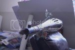
The Ping-Pong version of the Navigation Island seems too high, even though the spotting top clears it nicely. It just sticks up too much at the bow.
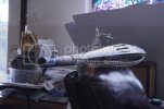
New Nav Island idea: faceted Christmas ornament Ball and tape spool (the tape spool is just there to give it height and keep it in place.) The final Nav Island will be mounted on pylons attached magnetically to the hull.
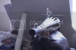
Not immediately obvious from my old profile drawings is the idea of an 'ordnance bridge' a structure that sits on the hull aft. Here I'm trying to rough out the general width of that part with a bit of cardboard. The final piece will be built from styrene and, like the boom tower and the nav island attached magnetically to the hull for easy removal.
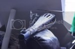
Wider piece of cardboard. Different nav island concept.
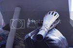
Testing the 'Side-Saddle' mounting of the boom tower. Multiple positions for the towers does two things at once: it illustrates the idea in Firadis that the boom towers on the dredges could traverse freely over the forward hull and it also creates multiple options for photographing variations. In combination with different spotting tops and hull sizes, this means with one build and a few extra parts I will be able to model multiple vessels, for the Firadis website.
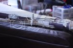
Boom tower base holding, but just barely. When we photograph the completed model in this config, we will help the boom tower out with a little fishing-line support to remove the bowing caused by gravity, unavoidable with these materials.
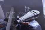
You may have noticed the hull seems longer in these photos. It has a 7 & 1/2 inch extension (culled from the first cardboard dredge attempt) that I felt improves the profile immensely and helps with the height of the tower. Here I have removed the extension and restored the hull to its former length, with the tower mounted on the aft mount position and the ping-pong nav island standing in.

Aggressive head-on. Never even attempted to draw such a shot. Modeling has its advantages...
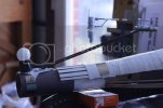
With the 'short hull' version of the dredge, in combination with multiple spotting tops and different boom positions, I will be able not only to model the Vaal Ilaan, featured in Firadis (Arena) but several of her foes as well, at least four or five dredges all together. In this 'short hull' configuration with the boom tower mounted at the extreme bow, the base will have to be combined with a suitable nav-island that can be attached.
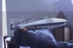
Profile of the original 'short hull' variant.
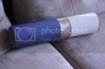
Hull extension made from the same kind of document tube as the inner hull. This will also be removable as the dredge mechanism at the extreme bow will be both complex and delicate. A much shorter dredge mechanism part will be built to fit the 'short hull' variant.
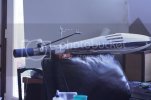
'Long-Hull' version for comparison. Much more pleasing to my eye.
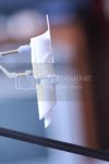
The spotting top attached using the upper two attachment points. It seems to come very close to the boom to my eye, and looks a bit 'crowded.'
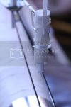
However, when viewed from above on the quarter the open space between the double boom seems to help.
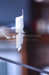
Using the lower attachment points, the spotting top clears the boom better, but adds height, which I'm trying to limit.
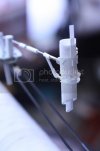
Comparison view.
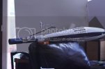
I think I'm not going to be happy testing these proportions until I've detailed the spotting top with all of its antennas and spines, which will give me the final height of the whole assembly. At that point we'll be able to see if the proportions work.
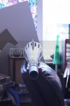
Symmetry check. Boom is much more stable with the spacer-block between the CF rods. It will be more stable still when it is glued in place.
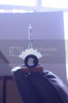
Dead-on looking straight down the hull axis. This will not be hollow when finished, of course. ;D I had not planned to light this model. It seemed to me for my first serious SF scratch-build to be complex enough as it is. Also 'window lights' will be easy to add in photoshop, and much less time consuming.
However, the dredge intake (Bussard ram-scoop) will have detail that extends into the forward hull. This will not be visible without some sort of internal lighting, particularly with the low levels of light we'll be using in the studio. The same applies to the engines. As it happens I have some clear plastic cups I'm planning on using to create the internal cavities at both ends of the ship. I may go ahead and mount some internal LED's to light the extremities internally. Still mulling this over.
That's all for now. Happy Modeling!
Hello!
Hope everyone is doing well!
Two things have happened recently, my fourth daughter was born, and my home computer died. I am writing this on a borrowed laptop. I hope to be back with more updates soon. The model continues to progress. I will post more when I have my computer repaired, or when I'm able to obtain a new one.
In the meantime, Happy Modeling!
Similar threads
- Replies
- 28
- Views
- 2K
- Replies
- 5
- Views
- 729
