Voyager from Fantastic Voyage Cartoon

Here are the latest photos.

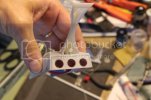
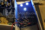
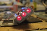
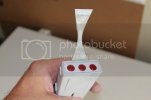
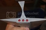
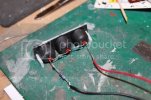
Engine vent wiring:
IMG_1753_2.jpg

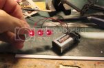
Three 3mm red LEDs wired in series with 10 ohm resistor.

Engine vent light test:
IMG_1755_2.jpg

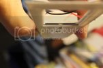
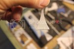
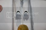
Engine vent covers:
IMG_1756_2.jpg

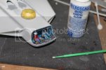
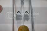
Clear plastic covers cut from thin clear sheet styene then press fit (they fit snugly) then glued with Micro Kristal Klear. The covers were needed to give the stern engine vent decals a flat surface to be applied to.


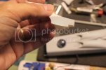
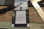
Dymo label tape:
IMG_1774_2.jpg

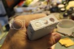
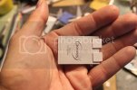
The Dymo tape serves as a guide for the scribing tool I used to cut an access panel out of the lower hull.

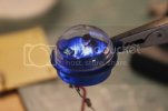
Busby Birdwell in his pilot seat:
IMG_1770.jpg
IMG_1772.jpg

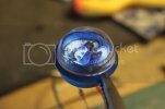
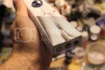
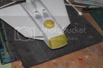
Clear dome was attached to cockpit with Krestal Klear and lit up. The light was bright enough to shine thru the white plastic and illuminate the instrument panel from below.

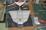
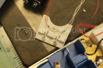
Ceiling panel wiring:
IMG_1777_1.jpg

LEDs posiitoned to be directly above cabin seats. Two forward LEDs wired in series with 150 ohm resistor. Rear LED will be in series with cockpit light.

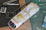
Upper and lower hull halves:
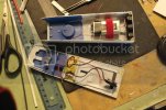
IMG_1779.jpg

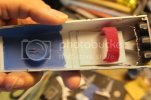
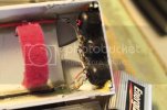
The cabin ceiling is painted Bright Blue to match the rest of the interior. The negative battery lead is wired to the pushbutton switch which has been glued and packed with Tamiya epoxy putty to ensure it will NEVER break loose. The battery is held in place to the upper hull half with a velcro tie strap.

Next up is decaling the instrument panel in the bow of the ship and gluing Erica Cane, Jonathan Kidd, and Guru into their seats before gluing the seats to the cabin floor. Then I'll finish wiring up the LEDs to the negative pushbutton and positive battery leads before sealing the hull up.

As always, thanks for following along. Comments appreciated!
 
More pics from last night and this morning...

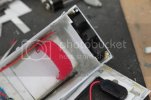
I realized I didn't show much detail concerning the battery compartment and how I rigged the strap so I took a few more pics to illustrate...


Velcro Strap Platform:
IMG_1781.jpg

The strap slides snuggly thru slots I carved in a section of thick styrene sheet which was then glued into the upper hull with styrene cement and CA.
Part of the slot that the tail fits into had to be removed to created a shelf for gluing the platform to on the back end. It also allows for more clearance as it's a tight fit with a 9V battery.


Access Door Panel:
IMG_1786.jpg

Tabs were glued using Testors tube cement. I still haven't decided on how to secure the other end of the panel to the rear of the ship.
I'll either use a magnet or screw.


Access Door Slots:
IMG_1788.jpg

Two thicknesses of styrene sheet were cut and stacked to make slots that the door tabs slide into.

Mounting Tube:
IMG_1780.jpg
IMG_1784.jpg

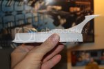
I'm planning to take photographs of Voyager in flight mode (as well as on the kit stand) so I decided it would be a good idea to include a mounting tube somewhere on the ship.
The stern felt like an obvious choice so I glued a short piece of Evergreen tubing to a matching length of Evergreen I-Beam tubing which was glued into the tail slot using Testors tube glue.
I didn't use CA as I've found under certain loads CA can pop loose.
Nothing welds styrene together better than styrene cement glues.
Although the cartoon images on the net don't show this opening in the stern I figure it makes sense as a port for launching various probes or even as a laser mounting point to ward off attackers chasing Voyager during one of her many daring missions.


Tail:
IMG_1783.jpg

I had to cut a slot in the front at the base of the tail to allow for the battery platform protruding thru from inside the ship.
No big deal.


Tail Insert:
IMG_1785.jpg

This is the cover for the backside of the tail. A hole will need to be drilled for the mounting tube to pass thru.
Before it's glued in place though I'll pack the inside of the tail with AVES apoxy sculpt for added strength.
It may seem like overkill but it won't hurt and I want that mounting tube to stay put dammit!


Gratuitous Profile Pic:
IMG_1789.jpg

What can I say... just a sweet design from any angle.

As the weekend approaches I'm looking forward to finishing up the wiring and guing the hull together.
Then the tail and wings go on and I start to putty and sand the gaps.

Thanks for reading along. More to come!
;D
 
[B]Updates from this past weekend for my fellow addicts...[/B]

The wiring was changed to a parallel circuit for all the LEDs. This required more wires and resistors so it looks messier but it works:
IMG_1805.jpg
IMG_1806.jpg
IMG_1807.jpg

The LEDs burn nice and bright now!

After testing to be sure all connections were solid I gave all exposed solder joints a coat of MMM Liquid Electrical Tape to insulate the postitive from the negative. This should avoid any short circuits when I close up the hull halves.

I didn't want the battery butting up against exposed LED engine wiring so a styrene panel was cut and glued into the stern to form the rear wall of the battery compartment. AVES was then packed around it for added strength:
IMG_1808.jpg

The hull glued together and held tight with rubber bands:
IMG_1809.jpg

And better yet the lights still functioned!

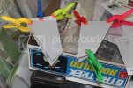
Wings were glued together with Testors styrene cement and clamped:
IMG_1811.jpg

The tailfin was glued with Testors and packed with AVES. AVES also filled in any gaps around the insert. You can see the tube where a brass rod can be inserted for support.:
IMG_1813.jpg

Wings were attached with Testors styrene cement and rubber banded to dry overnight:
IMG_1816.jpg

The horizontal stabilizer isn't glued on yet, I just placed it on top of the vertical tailfin for the picture.

So the next thing is to fill any hull/wing gaps with AVES before finish sanding.

Thanks for following along as this build nears completion! We're getting there now!
 
I remember seeing the movie when i was a kid but never saw the cartoon.

Those figures look realy tiny, great job on the painting

This is a realy nice looking build

Gag
 
So she's about ready for another white primer coat. Still need to attach the horizontal stabilizer to the tailfin.
I used AVES Apoxy Sculpt putty on the wing and tail seams (there were some serious gaps) and let dry overnight then sanded that down to about 600 grit.
I love this stuff, it smooths out and feathers in so easily using mostly just my fingers and some saliva.
I used to have a bottle of Safety Solvent but that jumped off the table and rolled away I guess as I can't seem to find it now. No big deal-spit will do!
Next I applied some Tamiya Basic Type polyester putty; let dry overnight and sanded down to about 1200 grit.
Any remaining minor scratches I covered over with Mr Surfacer 1000.


Stern:
IMG_1819.jpg

Intake Vents:
IMG_1820.jpg

I separated the bow window carefully from the parts tree and sanded the edges with medium and fine sanding sticks to get it to fit;
initially there were some gaps along the bottom sides of the window and the window did not sit quite flush along the top but after some sanding she fit flush along the top and the gaps disappeared.
Once the window was ready for install but before gluing the window to the model I stuck on a piece of masking tape and pressed it down as snug as I could with my fingers all around the edge of the window before trimming the tape using a flat needle file and fine grade sanding sticks.


Window glued on with Kristal Klear:
IMG_1821.jpg

Masking tape applied once glue had dried:
IMG_1822.jpg

Next I'll attach the horizontal stabilizer and mask off the engine vents.

:)
 
Well you gotta add one then. I thought maybe it was some idiosyncracy of where the mold halves separate.
 

Latest posts

Back
Top