Revell 1/48 Lunar Module
- Thread starter Jim2001
- Start date
Grendels
Active Member
- Joined
- Nov 24, 2009
- Messages
- 9,092
Jim: It won't shrink up that much. I just covered a 32 inch by 22 inch piece of wood with it and I think the shrinkage was around an 1/8 inch.
But I also covered a 12 inch piece of thin wood with it and it warped the wood so it is no longer round.
I did not have that problem in the past. Here is what I did differently: This time I followed the directions straight up. In the past I used half water and half PVA glue.
Also, this time around, I really didn't have time for it to cure up normally, so I put the pieces I was working on in a very hot environment, around 150F to speed curing. In the past I let it cure at room temp.
Jim2001
Member
- Joined
- Jun 11, 2009
- Messages
- 58
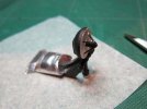
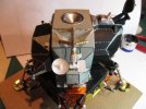
I originally made the rendezvous radar by filling in the dish part with putty and sanding it smooth. I then added small pins and CA glue with baking soda to join them to a central post. I never really liked the look of this so I broke it off and started again.
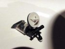
I covered the dish with a circle of very thin styrene and then made the correct shaped brackets and central post. The dish surface is smaller than a dime.
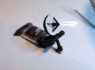
Here it is with black paint. I still have to add a few small dots to the dish face but I'm much happier with how it looks now.
I'm continuing on with mounting the antennae to the mid-section, then the docking target.
13aceofspades13
lets kick some tires and lights some fires!
- Joined
- Oct 12, 2010
- Messages
- 2,292
wow man, looots of detail, great job man XD
Jim2001
Member
- Joined
- Jun 11, 2009
- Messages
- 58
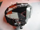
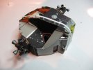
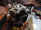
I've completed the EVA hand rail running up the left side of the hatchway and over to the roof of the ascent stage. There is still one support missing at the top, but it's easy to add later. A fine pin will be a perfect support here.
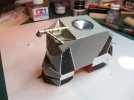
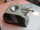
The port S-band antenna mast is complete and installed with silver foil and Kapton tape wraps. This one is easier than the other antennae due to it's size. The 3 smaller ones will be much more fussy.
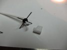
Here is a start on one of two identical VHF antennae. I drilled small holes with a pin-vise and inserted very fine steel pins, snipped them, painted them black and then dipped the tips in white a few times to make them slightly bulbous. Also you can see a scratch built part for the S-band antenna mount. This now has to be painted half black and half white.
13aceofspades13
lets kick some tires and lights some fires!
- Joined
- Oct 12, 2010
- Messages
- 2,292
lots more XD
Quaralane
Well-Known Member
- Joined
- May 22, 2009
- Messages
- 11,263
I'll second this.Grendels said:Shakes head:
The detail is astounding!!!!
mallagoodee
New Member
- Joined
- May 27, 2011
- Messages
- 10
Oh-h-h-h man .... this is looking go-o-o-od!!!
You're really pulling out all the stops on this LM aren'tcha?
On the S-Band, don't try to replace the dish, but if anything, redo the horn inside the dish. But, this one, as it is right now, looks just fine!
This is my kind of eye-candy! Keep up the great work Jim!
Pete
You're really pulling out all the stops on this LM aren'tcha?
On the S-Band, don't try to replace the dish, but if anything, redo the horn inside the dish. But, this one, as it is right now, looks just fine!
This is my kind of eye-candy! Keep up the great work Jim!
Pete
Jim2001
Member
- Joined
- Jun 11, 2009
- Messages
- 58
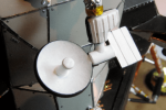
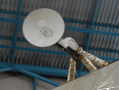

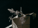
Thanks (all) for your kind words. It's definitely a fun project. Every time I look at my references I see something new. Sometimes I feel that given the scale I need to draw a line at some levels of detail. Either that or buy a microscope!
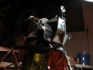
@mallagoodee: Here are my references of the S-Band Antenna (the top image is a closeup of mine). Yeah the support stem of the horn is kind of thick but I think I'll leave it and just add the oval of silver dots. If I did redo the dish I think I'd probably just redo the whole thing again as there are some details missing due to scale. I've redone this part several times and each time it's better but not perfect. I think I'll quit while I'm ahead.
ModelMakerMike
"It's Slobberin' time""
- Joined
- May 28, 2011
- Messages
- 1,838
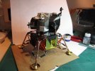
Looks like it's ready to land on the Moon! Fantastic work!
mallagoodee
New Member
- Joined
- May 27, 2011
- Messages
- 10
I've built 3 1/48 LMs and only on one, did I make a new S-band dish. It wasn't worth the effort. It's such a small detail ... but the other 2, I sanded down the dish ... and IIRC just using my finger wrapped with sandpaper. It knocked down the thickness nicely. But nobody noticed anyways ... :
And for the 'spots' on the dish, I used a mini-drill and made shallow holes. I found I had more control rather than trying to get the dots all alike with a paintbrush, or toothpick and my big, clumsy, shaky hands!
And those grooves you've got on the 'box' part of the S-band, they're raised, not grooves. That's not a critique, but just FYI.
I look forward to your updates Jim ... you're doing a terrific job on this!
Jim2001
Member
- Joined
- Jun 11, 2009
- Messages
- 58
I've built 3 1/48 LMs and only on one, did I make a new S-band dish. It wasn't worth the effort. It's such a small detail ... but the other 2, I sanded down the dish ... and IIRC just using my finger wrapped with sandpaper. It knocked down the thickness nicely. But nobody noticed anyways ...
That's my fear too. It may be too small for such attention.
And for the 'spots' on the dish, I used a mini-drill and made shallow holes. I found I had more control rather than trying to get the dots all alike with a paintbrush, or toothpick and my big, clumsy, shaky hands!
I like the drill idea. I was going to try using a pin dipped in silver paint. I did this with the rivets on the ascent section.
And those grooves you've got on the 'box' part of the S-band, they're raised, not grooves. That's not a critique, but just FYI.
Yes I made them grooves because that was easier. If I redo it I will make them raised.
I look forward to your updates Jim ... you're doing a terrific job on this!
Cheers!
ShutterAce
Active Member
- Joined
- Mar 31, 2011
- Messages
- 1,043
AWESOME ;D ;D ;D
Grendels
Active Member
- Joined
- Nov 24, 2009
- Messages
- 9,092
ShutterAce said:AWESOME ;D ;D ;D
Couldn't have said it better....
Jim2001
Member
- Joined
- Jun 11, 2009
- Messages
- 58
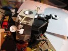
Here is a development I found really interesting and thought I'd post the info here for those who (like me) love this kind of detail. It was pointed out to me (much obliged Vincent) that the rendezvous radar dish (top front) was not pointing to the horizon while Apollo 11 Eagle was on the moon.
The reason I thought it was (and built it that way) is because of this image.

http://www.hq.nasa.gov/office/pao/History/alsj/a11/AS11-40-5863-69.jpg
I knew this image was a composite of at least 2 other images, but what I didn't realize is the images are not from the same LM. It turns out that while this image is indeed of the Eagle sitting on the lunar surface, the upper portion of the ascent stage was out of frame and the radar dish was taken from an image of Apollo 14's Antares LM. I couldn't find the actual image used but here you can see Antares with the dish pointing down at the ladder.

http://www.hq.nasa.gov/office/pao/History/alsj/a14/AS14-66-9255HR.jpg
Antares was apparently the only LM who's rendezvous radar dish was pointing somewhat to the surface and not up at zenith as in this image of Apollo 11.

My rendezvous radar was easy to correct since I had built the parts gimballed with small pins so they rotated freely. My RR is now pointing in the right direction.
The Apollo Image Gallery can be found here, and contains all the images from all the missions:
http://www.apolloarchive.com/apollo_gallery.html
The reason I thought it was (and built it that way) is because of this image.

http://www.hq.nasa.gov/office/pao/History/alsj/a11/AS11-40-5863-69.jpg
I knew this image was a composite of at least 2 other images, but what I didn't realize is the images are not from the same LM. It turns out that while this image is indeed of the Eagle sitting on the lunar surface, the upper portion of the ascent stage was out of frame and the radar dish was taken from an image of Apollo 14's Antares LM. I couldn't find the actual image used but here you can see Antares with the dish pointing down at the ladder.

http://www.hq.nasa.gov/office/pao/History/alsj/a14/AS14-66-9255HR.jpg
Antares was apparently the only LM who's rendezvous radar dish was pointing somewhat to the surface and not up at zenith as in this image of Apollo 11.

My rendezvous radar was easy to correct since I had built the parts gimballed with small pins so they rotated freely. My RR is now pointing in the right direction.

The Apollo Image Gallery can be found here, and contains all the images from all the missions:
http://www.apolloarchive.com/apollo_gallery.html
Similar threads
- Replies
- 11
- Views
- 559
- Replies
- 24
- Views
- 1K
- Replies
- 27
- Views
- 2K

