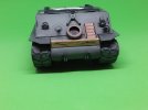
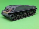
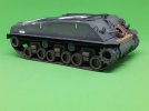
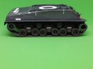
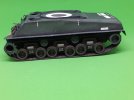
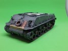
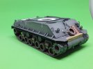
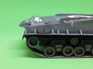
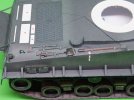
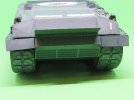
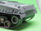
Sherman M4A3E8 "Easy Eight" Paper Model

Thank you Patrick.
They are working out well and almost work like rubber track.

Jim
 
Looking great. The bogies have hubs that are set back into the cylinder. I am still wondering how that worked.

-Steve
 
Thank you Steve.
The Bogies consist of 5 pieces, the outer tube, a narrow tube for the inside, around insert for the centre, a front ring and a disk for the back. The narrow tube inserts into the front of the main tube at the front. The round insert is glued into the main tube butting up to the back of the narrow tube. Then the front ring and back disk are glued into place.

sherman_fury_assembly_8_zpsbsmxnqlo.jpg

Hope that explains the bogie construction.

Jim
 
Papermodder said:
The Bogies consist of 5 pieces, the outer tube, a narrow tube for the inside, around insert for the centre, a front ring and a disk for the back. The narrow tube inserts into the front of the main tube at the front. The round insert is glued into the main tube butting up to the back of the narrow tube. Then the front ring and back disk are glued into place.

Hey Jim,
So you are gluing paper joints that are just butted together. That sounds very intricate. Are you working from a kit or custom design and paper prints? Either way its pretty amazing what you can do with detailed origami.

-Steve
 
For certain structures butt joints are the preferred method. Glue tabs can leave a lap joint that is not desirable.
On box structures, glue tabs are fine in most cases. Edge gluing is not that difficult with the type of card we are using. It's just glue the edge and clamp it till dry, but small diameter tubes can be tricky.
This kit is a downloaded template that I print out. I do have some preprinted kits in my stash.

Jim
 
Good day.
Time for an update on my Sherman.
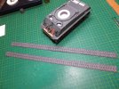
Yesterday The last of the track pads were installed onto the 2nd track.

Track%206_zpswlhd2kzz.jpg

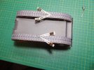
When they dried, the tracks were glued together around the drive train, with a butt joint and left to dry.

Track%207_zpsfrt8aqwh.jpg

Today, I went around and stablized the track to the drive train. Added some sag to the track where it is normally seen.

Track%208_zps1rrk36jc.jpg

Track%209_zpsmuipjtub.jpg

Track%2010_zpsdqcgqsg7.jpg

Track%2011_zps4zdldt0l.jpg

Track%2012_zpsebdnpuh0.jpg

Adding the track has really made the hull pop and look more like her namesake.
Now on to adding more detail pieces to the hull.

Thank you for following.
Questions and comments welcome.

Jim
 
Very Nice work Jim..
It is starting to look like it has some weight to it now..
Do the front drive wheels get the rest of their cogs now ?
Really liking this build, will be following
Cheers
 
Thank you Bruce.
No, this is how the designer made that part. I believe he was trying to give the illusion of the drive meshed with the track.

Jim
 
Good afternoon.
I've been working this week on adding more of the hull's details.
Started off with adding all the brackets for the mud shrouds. Fairly simple just have to take your time.

Hull%20Details%201_zpsimufpoys.jpg

Hull%20Details%202_zpsxrisv0iy.jpg

Hull%20Details%203_zpsxl7gvinl.jpg

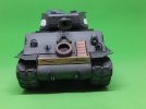
The supplied what was suppose to be the spare track was just a box that did not look at all like the track. Using the two pieces of track left over from shortening the main track. I constructed two spare track and mounted them to 2mm card for depth. these were then mounted to the hull.

Hull%20Details%204_zps7fqob0d7.jpg

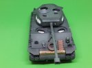
Next up were the tools. These were too simplified looking for my taste and needed detailing. Added all the missing brackets. The shovel had the handle cut out and the blade shaped. It was then repainted. The position for the shovel as defined by the kit was all wrong. It had to be moved more up onto the deck.

Hull%20Details%205_zpsnpfrtjzu.jpg

The tail lights were then constructed and I painted in the missing lens. These were mounted with their brackets as were the rear grabs.
There is stowage that will be mounted to the rear of this tank. As it was, they would just look like they were floating on the back with no support. The fold up carrier on the back is not there. This was easy enough to scratch and mounted into position.

Hull%20Details%206_zpssa3a8vgn.jpg

Hull%20Details%207_zps1rnibh6l.jpg

The last thing that was added were the missing fuel caps. The guards were there but no caps.

Hull%20Details%208_zps1xx9mjhl.jpg

This is where I am at at this moment.

Thank you for following.
Questions and comments welcome.

Jim
 
Really interesting , Jim .

What do you think of the original plans overall ?
The one big issue IMO is that front drive sprocket . It doesn't scale to the track and the missing , meshed teeth really look odd if you give it any looking :p

Other than that , it's convincing enough .

Cheers !
 
Thank you Uru.
If you look at and actual Sherman, the drive sprocket teeth seem to disappear into the track and do not rise above them. If anything the diameter of the drive sprocket tube needs to be increased. Maybe tooth detail drawn onto that section of the sprocket.
 
;D Ha Ha --
I just returned to recant a bit and say just that .

I had been window shopping some Sherman kits -- I'm really fond of the M51 Super Sherman

...... but I was noticing that the design does a pretty good job representing the actual tank indeed .


Do you know what you will be building next ?

Uru
 
Hi Uru.
My father was a Tanker ( Sig picture) and I was raised around these tanks and was in the armour corp. myself for a while.
So the Sherman holds a special place for me.
As for whats next I have a couple of ideas, but am waiting till this is done and the start of the BSC to decide.

Jim
 
Good day.
I've switched gears for the moment and have started on the turret. I want to get the main body of the tank finished before adding all the stowage.
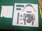
Turret%201_zpszqwzzpdk.jpg

I did add some thicker card to the turret ring and the deck of the turret to stiffen them up a bit.
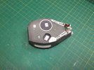
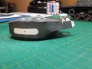
Turret%202_zpsuefgmvof.jpg

Turret%203_zpsosdypqyt.jpg

One tricky part was to figure out the right sequence to assemble it, so as not to get trapped.
The crew commander's cupola, I cut off the glue tabs and edge glued it, to make it neater. On the master weapon the break was opened up and coloured internally. I like this look better.
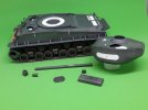
Turret%204_zps0x0q8dav.jpg

A couple more additions have been added to the turret. The spent shell extraction hatch to the side of the turret and the coaxial machine gun to the mallet, both of which were not with the design. I also opened up the telescope port on the mallet.
Two periscopes have now been install onto the turret, and the whole turret has been placed onto the hull. The turret pivot has not been glued inplace yet, just test fitted.
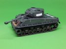
Turret%205_zpsy6g3yoht.jpg

The gunner's hatch has been installed.
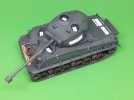
Turret%206_zpsfuxugdfb.jpg

Turret%207_zpsz1cdcpmm.jpg

Turret%209_zps9zu83oe0.jpg

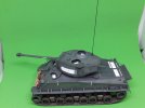
So far today the pivot for the turret has been glued into the turret and two brackets were installed to the rear of the turret. I also scratched and installed an antenna.
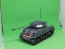
Turret%2010_zpsjnptiwib.jpg

Turret%2011_zpsrqjxgxqn.jpg

This is where I am at.

Thank you for following.
Questions and comments welcome.

Jim
 

Latest posts

Back
Top