Now… Voyager…
- Thread starter trekriffic
- Start date
trekriffic
Well-Known Member
- Joined
- Jan 6, 2012
- Messages
- 1,041
Way behind on postings. Lots going on. Picking up where we left off... I'll be bouncing around so hold on tight...
New flattened profile after more plastic and putty work on the fantail:
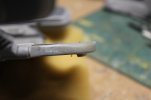
USS Voyager WIP Img - 179 by Steve J, on Flickr
New fantail window framing for a more recessed appearance:
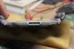
USS Voyager WIP Img - 180 by Steve J, on Flickr
He bounces...
In order for the shuttle bay to fit and sit level, I had to remove a layer of plastic from the hull
underneath the back section of the floor where it makes a left turn:
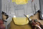
USS Voyager WIP Img - 181 by Steve J, on Flickr
I made this necessary when I added a thin piece of sheet sytrene under the rear section of the floor to stiffen it as the
printing material was so thin and soft. The hobby"dremel" made this a lot faster then it would have been otherwise.
Care had to be taken not to grind away too much and make a hole in the slot I was carving:
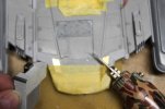
USS Voyager WIP Img - 181 by Steve J, on Flickr
Successful test fit of the new printed bay:
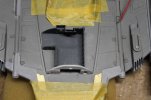
USS Voyager WIP Img - 182 by Steve J, on Flickr
The kit had a much shorter recess tailored to fit the parts in the kit which were much shorter. Only a thin layer of hull plastic remains as you can see here, i confess I went thru in a few spots but only just barely and no wires were damaged inside the hull:
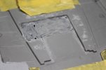
USS Voyager WIP Img - 183 by Steve J, on Flickr
Test fitting shuttle bay to the modified hull slot I had to carve out atop the fantail:
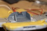
USS Voyager WIP Img - 184 by Steve J, on Flickr
He bounces...
Light blocking of fore and aft photon torpedo ports:
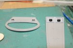
USS Voyager WIP Img - 187 by Steve J, on Flickr
He bounces again...
Shuttle bay and roof parts airbrushed color "J" per the model makers painting instructions. This is a 50/50 mix of grey and light grey enamels:
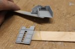
USS Voyager WIP Img - 188 by Steve J, on Flickr
The slot I carved in the hull to accommodate the floor of the shuttle bay was sanded and filled with white acrylic putty to smooth out the divots:
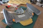
USS Voyager WIP Img - 195 by Steve J, on Flickr
Stand by for another fantastic update tomorrow...
New flattened profile after more plastic and putty work on the fantail:

USS Voyager WIP Img - 179 by Steve J, on Flickr
New fantail window framing for a more recessed appearance:

USS Voyager WIP Img - 180 by Steve J, on Flickr
He bounces...
In order for the shuttle bay to fit and sit level, I had to remove a layer of plastic from the hull
underneath the back section of the floor where it makes a left turn:

USS Voyager WIP Img - 181 by Steve J, on Flickr
I made this necessary when I added a thin piece of sheet sytrene under the rear section of the floor to stiffen it as the
printing material was so thin and soft. The hobby"dremel" made this a lot faster then it would have been otherwise.
Care had to be taken not to grind away too much and make a hole in the slot I was carving:

USS Voyager WIP Img - 181 by Steve J, on Flickr
Successful test fit of the new printed bay:

USS Voyager WIP Img - 182 by Steve J, on Flickr
The kit had a much shorter recess tailored to fit the parts in the kit which were much shorter. Only a thin layer of hull plastic remains as you can see here, i confess I went thru in a few spots but only just barely and no wires were damaged inside the hull:

USS Voyager WIP Img - 183 by Steve J, on Flickr
Test fitting shuttle bay to the modified hull slot I had to carve out atop the fantail:

USS Voyager WIP Img - 184 by Steve J, on Flickr
He bounces...
Light blocking of fore and aft photon torpedo ports:

USS Voyager WIP Img - 187 by Steve J, on Flickr
He bounces again...
Shuttle bay and roof parts airbrushed color "J" per the model makers painting instructions. This is a 50/50 mix of grey and light grey enamels:

USS Voyager WIP Img - 188 by Steve J, on Flickr
The slot I carved in the hull to accommodate the floor of the shuttle bay was sanded and filled with white acrylic putty to smooth out the divots:

USS Voyager WIP Img - 195 by Steve J, on Flickr
Stand by for another fantastic update tomorrow...
trekriffic
Well-Known Member
- Joined
- Jan 6, 2012
- Messages
- 1,041
Darting here and there...
Reworked deep rear window and squared up fantail before cleanup. Shuttle bay test fitting:
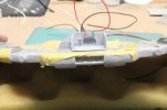
USS Voyager WIP Img - 199 by Steve J, on Flickr
Shuttle bay test fit. Fantail masked to protect fiber for lights:
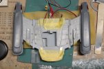
USS Voyager WIP Img - 200 by Steve J, on Flickr
Fantail inserted into rear of secondary hull. No glue yet:
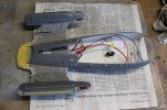
USS Voyager WIP Img - 202 by Steve J, on Flickr
The roof was prone to bending so I reinforced it using a piece of leftover Paragrafix brass photo-etch.
It was just about the perfect shape to fit the length of the ceiling light slot now covered by a piece of sanded clear styrene.
The roof can still be bent if needed but it's much more rigid than before and will not be prone to sagging especially if exposed to heat:
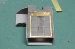
USS Voyager WIP Img - 203 by Steve J, on Flickr
Deflector dish test fitting into hull and taping for measurements. Ventral secondary hull strobe LED with fiber glued in place:
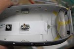
USS Voyager WIP Img - 207 by Steve J, on Flickr
I needed to protect the belly strobe fiber optic strand from being broken off during the next phase of work.
So I cut a short piece of Evergreen tubing to form a round wall around the fiber.
Tamiya tape holds the fiber "shield wall" in place:
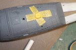
USS Voyager WIP Img - 208 by Steve J, on Flickr
Back wall of deflector reflector housing has a blue 3 mm wide LED tape strip centered vertically and horizontally for illuminating the back of the clear (sanded) dish:
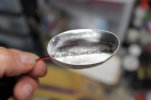
USS Voyager WIP Img - 210 by Steve J, on Flickr
Deflector dish held up against the deflector housing and lit by a blue LED strip.
This is before I add the diffusion discs of thin styrofoam sheet and a disc of clear blue styrene.
This is also before I made the ribs around the perimeter opaque using strips of white decal paper painted with orange-brown enamel:
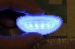
USS Voyager WIP Img - 211 by Steve J, on Flickr
I brushed this adhesive onto each rib on the clear deflector dish using a "superfine" microbrush.
Then I placed a small orange-brown strip made of white decal material carefully onto the rib using tweezers before burnishing with a cotton swab:
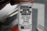
USS Voyager WIP Img - 212 by Steve J, on Flickr
After adding thin decal strips to each rib but before I clean up the tips, do some paint detailing with a fine tipped brush, or finish the center ring using more of the orange-brown decal material. The very center will either be painted or covered with a disc of white decal:
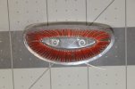
USS Voyager WIP Img - 214 by Steve J, on Flickr
Next up... more light tests.
Reworked deep rear window and squared up fantail before cleanup. Shuttle bay test fitting:

USS Voyager WIP Img - 199 by Steve J, on Flickr
Shuttle bay test fit. Fantail masked to protect fiber for lights:

USS Voyager WIP Img - 200 by Steve J, on Flickr
Fantail inserted into rear of secondary hull. No glue yet:

USS Voyager WIP Img - 202 by Steve J, on Flickr
The roof was prone to bending so I reinforced it using a piece of leftover Paragrafix brass photo-etch.
It was just about the perfect shape to fit the length of the ceiling light slot now covered by a piece of sanded clear styrene.
The roof can still be bent if needed but it's much more rigid than before and will not be prone to sagging especially if exposed to heat:

USS Voyager WIP Img - 203 by Steve J, on Flickr
Deflector dish test fitting into hull and taping for measurements. Ventral secondary hull strobe LED with fiber glued in place:

USS Voyager WIP Img - 207 by Steve J, on Flickr
I needed to protect the belly strobe fiber optic strand from being broken off during the next phase of work.
So I cut a short piece of Evergreen tubing to form a round wall around the fiber.
Tamiya tape holds the fiber "shield wall" in place:

USS Voyager WIP Img - 208 by Steve J, on Flickr
Back wall of deflector reflector housing has a blue 3 mm wide LED tape strip centered vertically and horizontally for illuminating the back of the clear (sanded) dish:

USS Voyager WIP Img - 210 by Steve J, on Flickr
Deflector dish held up against the deflector housing and lit by a blue LED strip.
This is before I add the diffusion discs of thin styrofoam sheet and a disc of clear blue styrene.
This is also before I made the ribs around the perimeter opaque using strips of white decal paper painted with orange-brown enamel:

USS Voyager WIP Img - 211 by Steve J, on Flickr
I brushed this adhesive onto each rib on the clear deflector dish using a "superfine" microbrush.
Then I placed a small orange-brown strip made of white decal material carefully onto the rib using tweezers before burnishing with a cotton swab:

USS Voyager WIP Img - 212 by Steve J, on Flickr
After adding thin decal strips to each rib but before I clean up the tips, do some paint detailing with a fine tipped brush, or finish the center ring using more of the orange-brown decal material. The very center will either be painted or covered with a disc of white decal:

USS Voyager WIP Img - 214 by Steve J, on Flickr
Next up... more light tests.
trekriffic
Well-Known Member
- Joined
- Jan 6, 2012
- Messages
- 1,041
Thanks Q!
Now is time for more light tests and other things...
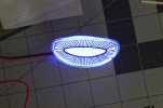
Light test using reflector tube housing behind clear/sanded dish.
This is with a single disc of transparent blue styrene and about 6 sheets of thin styrofoam sheet all trimmed to the oval shape of the tube stuffed in over the blue LED strip on the back wall:
USS Voyager WIP Img - 215 by Steve J, on Flickr
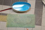
The deflector dish housing with the blue LED strip covered by one disc of transparent blue styrene.
Later I will add 6 layers of thin styrofoam packing sheet.
I also traced the housing's shape onto masking tape covering another piece of the same transparent blue styrene to be cut out into an oval ring:
USS Voyager WIP Img - 216 by Steve J, on Flickr
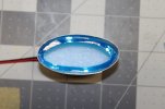
The darker blue ring was painted with Tamiya transparent blue acrylic (2 heavy coats) and CA glued at a distance about midway between the back of the fogged plastic deflector dish and the foam diffuser materia:
USS Voyager WIP Img - 217 by Steve J, on Flickr
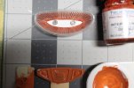
Deflector dish will be sealed with future clear acrylic before getting a few sprays with Dullcote.
I want a flat finish like the studio model.
Once fully cured the "orange ochre" center array will be masked and the remaining colors airbrushed on to finish the main and secondary deflector:
USS Voyager WIP Img - 219 by Steve J, on Flickr
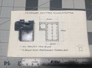
I made a drawing for adding stripes to the floor of the shuttle bay:
USS Voyager WIP Img - 221 by Steve J, on Flickr
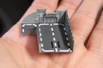
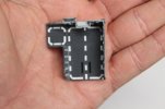
Shuttle bay after I used hand trimmed white, black, and red decal material to stripe the floor. I then I gave the floor a brushing with 2 coats of Future acrylic floor polish:
USS Voyager WIP Img - 221 by Steve J, on Flickr
USS Voyager WIP Img - 221 by Steve J, on Flickr
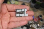
Interior of roof was retouched after brush painting with enamels:
USS Voyager WIP Img - 221 by Steve J, on Flickr
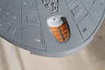
Deflector panels retouched with enamel orange ochre custom mixed and brushed on.
Some cleanup is needed but I'm pretty happy with how this is going:
USS Voyager WIP Img - 222 by Steve J, on Flickr
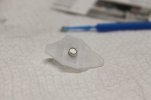
I glued a 1/8" x 1.5mm rare earth magnet inside a styrene ring in the underside of the Delta Flier.
This magnet will grab hold of the fantail where I mounted an identical magnet inside so the Flier can sit securely attached to the shuttle bay porch:
USS Voyager WIP Img - 224 by Steve J, on Flickr
Next up... more work on the Delta Flyer and Aerowing and... starting work on backlit panels... FINALLY!
Now is time for more light tests and other things...
Light test using reflector tube housing behind clear/sanded dish.
This is with a single disc of transparent blue styrene and about 6 sheets of thin styrofoam sheet all trimmed to the oval shape of the tube stuffed in over the blue LED strip on the back wall:

USS Voyager WIP Img - 215 by Steve J, on Flickr
The deflector dish housing with the blue LED strip covered by one disc of transparent blue styrene.
Later I will add 6 layers of thin styrofoam packing sheet.
I also traced the housing's shape onto masking tape covering another piece of the same transparent blue styrene to be cut out into an oval ring:

USS Voyager WIP Img - 216 by Steve J, on Flickr
The darker blue ring was painted with Tamiya transparent blue acrylic (2 heavy coats) and CA glued at a distance about midway between the back of the fogged plastic deflector dish and the foam diffuser materia:

USS Voyager WIP Img - 217 by Steve J, on Flickr
Deflector dish will be sealed with future clear acrylic before getting a few sprays with Dullcote.
I want a flat finish like the studio model.
Once fully cured the "orange ochre" center array will be masked and the remaining colors airbrushed on to finish the main and secondary deflector:

USS Voyager WIP Img - 219 by Steve J, on Flickr
I made a drawing for adding stripes to the floor of the shuttle bay:

USS Voyager WIP Img - 221 by Steve J, on Flickr
Shuttle bay after I used hand trimmed white, black, and red decal material to stripe the floor. I then I gave the floor a brushing with 2 coats of Future acrylic floor polish:

USS Voyager WIP Img - 221 by Steve J, on Flickr

USS Voyager WIP Img - 221 by Steve J, on Flickr
Interior of roof was retouched after brush painting with enamels:

USS Voyager WIP Img - 221 by Steve J, on Flickr
Deflector panels retouched with enamel orange ochre custom mixed and brushed on.
Some cleanup is needed but I'm pretty happy with how this is going:

USS Voyager WIP Img - 222 by Steve J, on Flickr
I glued a 1/8" x 1.5mm rare earth magnet inside a styrene ring in the underside of the Delta Flier.
This magnet will grab hold of the fantail where I mounted an identical magnet inside so the Flier can sit securely attached to the shuttle bay porch:

USS Voyager WIP Img - 224 by Steve J, on Flickr
Next up... more work on the Delta Flyer and Aerowing and... starting work on backlit panels... FINALLY!
Last edited:
trekriffic
Well-Known Member
- Joined
- Jan 6, 2012
- Messages
- 1,041
Delta Flyer...
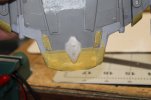
Delta Flyer resting on Voyager's fantail.
The magnets hold great. Not too strong but enough so you can't shake the shuttle off the hull:
USS Voyager WIP Img - 226 by Steve J, on Flickr
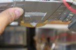
Magnet strength test by holding fantail upside down and shaking.
The shuttle stays put:
USS Voyager WIP Img - 228 by Steve J, on Flickr
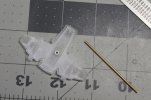
Worked on mounting tubes for Aero Wing display rod:
USS Voyager WIP Img - 229 by Steve J, on Flickr
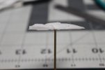
Aero Shuttle side view. This model is hollow but there are internal walls separating the main hull and the wing impulse engines so it will not be lit as it would require opening channels for either fiber or wires which would require marring the beautiful hull paneling of the printed part. I can use fluorescent paint to give me a pretty fair lit effect without the need to actually light it:
USS Voyager WIP Img - 230 by Steve J, on Flickr
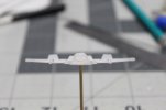
Aero shuttle bow on. I mounted it to a brass rod amidships. I will try to make it removable from the base:
USS Voyager WIP Img - 231 by Steve J, on Flickr
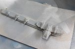
Shuttles get first primer spray, I didn't have to do much, if any, sanding before paint. Amazingly smooth for printed parts:
USS Voyager WIP Img - 232 by Steve J, on Flickr
Backlit window panels...
The material the backlit panels were printed on appears to be thin white styrene.
Either that or a heavy vellum die to its translucency but it glues like styrene.
I used CA to install them behind the clear plastic window panels.
It was so stiff I ended up treating it like photo-etch using some of the same tools:
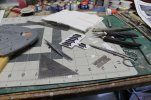
USS Voyager WIP Img - 233 by Steve J, on Flickr
Start of backlit panels in upper saucer. Black Tulip paint was brushed on to guard against light leaks after some putty had to be removed.
Almost all the panels needed some degree of trimming and bending with PE pliers to get them to fit properly.
This may be because I was using Paragrafix photo-etch for the window frames whereas the backlit panels were meant to work with the
Monogram kits clear window parts or even without any clear plastic windows.
At least that's the best explanation I can come up with for some of the fit issues:
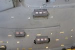
USS Voyager WIP Img - 237 by Steve J, on Flickr
Backlit panels light test:
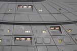
USS Voyager WIP Img - 234 by Steve J, on Flickr
Janeway's ready room and conference room backlit panels.
These were repurposed from panels meant for two single windows in the upper saucer.
Outer Space Outfitters didn't include panels for these so had to improvise:
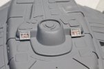
USS Voyager WIP Img - 236 by Steve J, on Flickr
Next... soldering wires...
Delta Flyer resting on Voyager's fantail.
The magnets hold great. Not too strong but enough so you can't shake the shuttle off the hull:

USS Voyager WIP Img - 226 by Steve J, on Flickr
Magnet strength test by holding fantail upside down and shaking.
The shuttle stays put:

USS Voyager WIP Img - 228 by Steve J, on Flickr
Worked on mounting tubes for Aero Wing display rod:

USS Voyager WIP Img - 229 by Steve J, on Flickr
Aero Shuttle side view. This model is hollow but there are internal walls separating the main hull and the wing impulse engines so it will not be lit as it would require opening channels for either fiber or wires which would require marring the beautiful hull paneling of the printed part. I can use fluorescent paint to give me a pretty fair lit effect without the need to actually light it:

USS Voyager WIP Img - 230 by Steve J, on Flickr
Aero shuttle bow on. I mounted it to a brass rod amidships. I will try to make it removable from the base:

USS Voyager WIP Img - 231 by Steve J, on Flickr
Shuttles get first primer spray, I didn't have to do much, if any, sanding before paint. Amazingly smooth for printed parts:

USS Voyager WIP Img - 232 by Steve J, on Flickr
Backlit window panels...
The material the backlit panels were printed on appears to be thin white styrene.
Either that or a heavy vellum die to its translucency but it glues like styrene.
I used CA to install them behind the clear plastic window panels.
It was so stiff I ended up treating it like photo-etch using some of the same tools:

USS Voyager WIP Img - 233 by Steve J, on Flickr
Start of backlit panels in upper saucer. Black Tulip paint was brushed on to guard against light leaks after some putty had to be removed.
Almost all the panels needed some degree of trimming and bending with PE pliers to get them to fit properly.
This may be because I was using Paragrafix photo-etch for the window frames whereas the backlit panels were meant to work with the
Monogram kits clear window parts or even without any clear plastic windows.
At least that's the best explanation I can come up with for some of the fit issues:

USS Voyager WIP Img - 237 by Steve J, on Flickr
Backlit panels light test:

USS Voyager WIP Img - 234 by Steve J, on Flickr
Janeway's ready room and conference room backlit panels.
These were repurposed from panels meant for two single windows in the upper saucer.
Outer Space Outfitters didn't include panels for these so had to improvise:

USS Voyager WIP Img - 236 by Steve J, on Flickr
Next... soldering wires...
trekriffic
Well-Known Member
- Joined
- Jan 6, 2012
- Messages
- 1,041
Jumping around like a glommer at a tribble convention...
All upper saucer large window backlit panels were glued in place. I used CA glue:
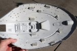
USS Voyager WIP Img - 238 by Steve J, on Flickr
The Shapeways Aero Wing, Delta Flyer, and other shuttles were primed with Krylon Colormaxx grey primer:
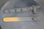
USS Voyager WIP Img - 239 by Steve J, on Flickr
A tube was added to allow passage of two wires and 5 fiber strands:
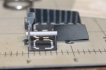
USS Voyager WIP Img - 241 by Steve J, on Flickr
Holes drilled in the starboard interior wall of the shuttle bay for very thin fiber optic strands. I would do the same to the opposite wall:
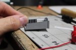
USS Voyager WIP Img - 242 by Steve J, on Flickr
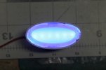
Deflector dish housing with blue clear styrene ring glued in place after housing was reinforced and stiffened using strips of .010 styrene strip wrapped around the outside. Light test:
USS Voyager WIP Img - 243 by Steve J, on Flickr
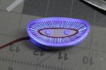
Deflector dish test fit in housing and lit up. The blue ring behind the dish looks amazing.
I wasn't sure it would create this effect so was very happy with how it turned out:
USS Voyager WIP Img - 244 by Steve J, on Flickr
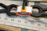
Dish glued into the deflector housing using Testors red tube glue and clamped to dry:
USS Voyager WIP Img - 246 by Steve J, on Flickr
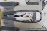
After the Testors glue dried I glued the deflector assembly in behind the mouth at the front of the secondary hull. I used Testors tube glue for this:
USS Voyager WIP Img - 247 by Steve J, on Flickr
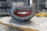
Deflector dish glued in place without incident. Looks pretty good from the front:
USS Voyager WIP Img - 248 by Steve J, on Flickr
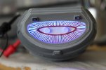
Light test:
USS Voyager WIP Img - 249 by Steve J, on Flickr
Next up... an unexpected problem solved...
All upper saucer large window backlit panels were glued in place. I used CA glue:

USS Voyager WIP Img - 238 by Steve J, on Flickr
The Shapeways Aero Wing, Delta Flyer, and other shuttles were primed with Krylon Colormaxx grey primer:

USS Voyager WIP Img - 239 by Steve J, on Flickr
A tube was added to allow passage of two wires and 5 fiber strands:

USS Voyager WIP Img - 241 by Steve J, on Flickr
Holes drilled in the starboard interior wall of the shuttle bay for very thin fiber optic strands. I would do the same to the opposite wall:

USS Voyager WIP Img - 242 by Steve J, on Flickr
Deflector dish housing with blue clear styrene ring glued in place after housing was reinforced and stiffened using strips of .010 styrene strip wrapped around the outside. Light test:

USS Voyager WIP Img - 243 by Steve J, on Flickr
Deflector dish test fit in housing and lit up. The blue ring behind the dish looks amazing.
I wasn't sure it would create this effect so was very happy with how it turned out:

USS Voyager WIP Img - 244 by Steve J, on Flickr
Dish glued into the deflector housing using Testors red tube glue and clamped to dry:

USS Voyager WIP Img - 246 by Steve J, on Flickr
After the Testors glue dried I glued the deflector assembly in behind the mouth at the front of the secondary hull. I used Testors tube glue for this:

USS Voyager WIP Img - 247 by Steve J, on Flickr
Deflector dish glued in place without incident. Looks pretty good from the front:

USS Voyager WIP Img - 248 by Steve J, on Flickr
Light test:

USS Voyager WIP Img - 249 by Steve J, on Flickr
Next up... an unexpected problem solved...
trekriffic
Well-Known Member
- Joined
- Jan 6, 2012
- Messages
- 1,041
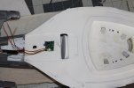
I had to carve out a slot in the back end flat section of the lower primary hull directly over the top rim
of the deflector housing as it interfered with attaching the lower saucer to the top of the secondary hull.
I could also use this slot to pass wires thru:
USS Voyager WIP Img - 250 by Steve J, on Flickr
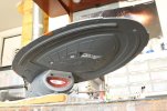
Test fit saucer bottom to engineering hull. Sweet:
USS Voyager WIP Img - 251 by Steve J, on Flickr
Ventral secondary hull and fantail flasher light test:
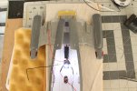
USS Voyager WIP Img - 252 by Steve J, on Flickr
LED strips, flashers, and red and green lights laid out in pencil with notations:
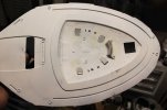
USS Voyager WIP Img - 253 by Steve J, on Flickr
White LED strip sections taped down prior to depositing solder droplets onto the copper wire contact points at each end:
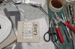
USS Voyager WIP Img - 254 by Steve J, on Flickr
Size M power jack and slide switch after gluing in wooden base using two part epoxy.
I will pack wood putty in around the switch to fill the gaps top and bottom.
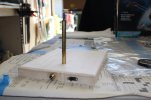
USS Voyager WIP Img - 257 by Steve J, on Flickr
Light test for lower primary hull strips:
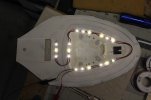
USS Voyager WIP Img - 255 by Steve J, on Flickr
Veering over here...
Underside of display base after wiring. Trenches will be filled with wood putty:
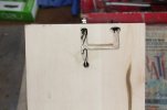
USS Voyager WIP Img - 256 by Steve J, on Flickr
Upper saucer interior light test with only the lower saucer half wired up and lit.
This will get somewhat brighter once I wire up and light he upper hull section too:
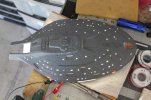
USS Voyager WIP Img - 258 by Steve J, on Flickr
Light test, upper hull, lit only by lights from lower hull LED strips:
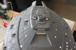
USS Voyager WIP Img - 259 by Steve J, on Flickr
Coning up... some shuttle and bay love...
of the deflector housing as it interfered with attaching the lower saucer to the top of the secondary hull.
I could also use this slot to pass wires thru:

USS Voyager WIP Img - 250 by Steve J, on Flickr
Test fit saucer bottom to engineering hull. Sweet:

USS Voyager WIP Img - 251 by Steve J, on Flickr
Ventral secondary hull and fantail flasher light test:

USS Voyager WIP Img - 252 by Steve J, on Flickr
LED strips, flashers, and red and green lights laid out in pencil with notations:

USS Voyager WIP Img - 253 by Steve J, on Flickr
White LED strip sections taped down prior to depositing solder droplets onto the copper wire contact points at each end:

USS Voyager WIP Img - 254 by Steve J, on Flickr
Size M power jack and slide switch after gluing in wooden base using two part epoxy.
I will pack wood putty in around the switch to fill the gaps top and bottom.

USS Voyager WIP Img - 257 by Steve J, on Flickr
Light test for lower primary hull strips:

USS Voyager WIP Img - 255 by Steve J, on Flickr
Veering over here...
Underside of display base after wiring. Trenches will be filled with wood putty:

USS Voyager WIP Img - 256 by Steve J, on Flickr
Upper saucer interior light test with only the lower saucer half wired up and lit.
This will get somewhat brighter once I wire up and light he upper hull section too:

USS Voyager WIP Img - 258 by Steve J, on Flickr
Light test, upper hull, lit only by lights from lower hull LED strips:

USS Voyager WIP Img - 259 by Steve J, on Flickr
Coning up... some shuttle and bay love...
trekriffic
Well-Known Member
- Joined
- Jan 6, 2012
- Messages
- 1,041
Thank you very much!Wow, this is impressive with all the lighting. You are doing great with it.
Here we go...
Shuttle craft love...
Shapeways 1/670 scale Type 9 shuttles painted and decaled. I used leftover decal material from my stash for the decals.
Some detail brush painting involved too.
Ignore the registry numbers,they are not accurate to Voyager's actual to shuttle reg numbers.
I couldn't get the correct ones in decals and they were much too small to paint.
Anyway, I figured once glued into the bay they won't be easily visible but I had to have something looking like numbers there on the sides of the shuttles:
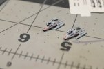
USS Voyager WIP Img - 262 by Steve J, on Flickr
Still a work in regress. Shuttle bay (I cut and paced decals piece by piece for the white striping), Delta Flyer, and two Type 9 shuttles.
The Delta Flyer barely fits in the bay:
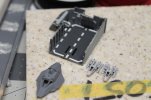
USS Voyager WIP Img - 263 by Steve J, on Flickr
Type 9 shuttles done except for final clear coat:
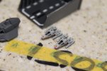
USS Voyager WIP Img - 264 by Steve J, on Flickr
Type 8 shuttle in bay alcove:
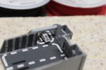
USS Voyager WIP Img - 265 by Steve J, on Flickr
Three shuttles glued into bay with all purpose clear liquid adhesive glue:
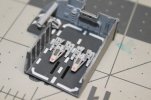
USS Voyager WIP Img - 266 by Steve J, on Flickr
Another shot of the shuttle bay with shuttles in place:
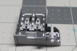
USS Voyager WIP Img - 267 by Steve J, on Flickr
Bay from above with shuttlecraft and fiber optics:
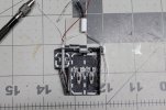
USS Voyager WIP Img - 269 by Steve J, on Flickr
A small 2 mm White LED is wired up to illuminate the alcove. Red and white 30 gauge wires
from the LED and fiber strands going to another LED inside the ship pass thru a tube into the forward part of the secondary hull:
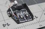
USS Voyager WIP Img - 270 by Steve J, on Flickr
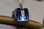
Shuttle bay ceiling light strip lit up:
USS Voyager WIP Img - 271 by Steve J, on Flickr
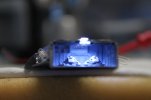
The cool white LED strip makes the grey interior of the blue look bluish in camera but it appears more like a light to medium grey to the naked eye:
USS Voyager WIP Img - 272 by Steve J, on Flickr
Next...
Some fantail priming and we begin installing the lights.
trekriffic
Well-Known Member
- Joined
- Jan 6, 2012
- Messages
- 1,041
Thanks! I just had to replace the awful kit provided bay and the shuttles really add to the realism.Most impressive work on the bay and the shuttles
trekriffic
Well-Known Member
- Joined
- Jan 6, 2012
- Messages
- 1,041
Yes. Thank god for my visor.Oh my goodness that is tiny. Absolutely fantastic.
trekriffic
Well-Known Member
- Joined
- Jan 6, 2012
- Messages
- 1,041
I am in a groove. Although I've run out of paint so hull painting is stalled.Awesome all around!
Moving inexorably to completion...
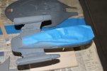
Fantail, nacelles, and secondary hull masked and primed with Krylon Colormaxx grey primer:
USS Voyager WIP Img - 273 by Steve J, on Flickr
And a short video...
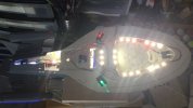
Test of always on strip and lighthouse LED lights in the lower saucer. Flasher wiring also done:
USS Voyager WIP Vid - 007 by Steve J, on Flickr
Bouncing over to the shuttle bay...
The two 30 AWG kynar alcove LED wires are passed thru a tubular conduit that crosses above a type 8 shuttle on the alcove floor
below to exit out the back wall and be soldered to the always on circuit wiring.
5 fibers from the shuttle bay port side entrance wall also had to be fed thru the same tight tube to then feed into
another tube attached to a 2mm white lighthouse style LED. Fibers from the starboard side wall also feed into this LED:
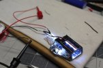
USS Voyager WIP Img - 275 by Steve J, on Flickr
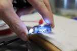
USS Voyager WIP Img - 276 by Steve J, on Flickr
She just fits! These type 9 shuttles look like triceratops IMO:
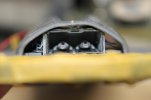
USS Voyager WIP Img - 277 by Steve J, on Flickr
Shuttle bay and main door wall glued in place.
Lights look pretty cool:
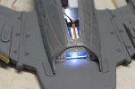
USS Voyager WIP Img - 278 by Steve J, on Flickr
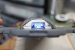
USS Voyager WIP Img - 279 by Steve J, on Flickr
Secondary hull wiring complete. Leads from power jack and flasher wiring ready for connection to lower saucer half:
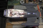
USS Voyager WIP Img - 280 by Steve J, on Flickr
Light test after installation of forward red photon torpedo LED's:
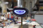
USS Voyager WIP Img - 281 by Steve J, on Flickr
I made notes in pencil for wiring on the white reflecting primer before soldering.
I went with the darkest setting I could find on my old Canon DSLR "creative" setting to take this very dimmed down shot:
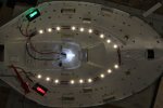
USS Voyager WIP Img - 274 by Steve J, on Flickr
Next time...
More wiring and some cool light tests.
Last edited:
Pantherman
Well-Known Member
- Joined
- Feb 10, 2022
- Messages
- 4,039
Fantastic work. PanthermanI am in a groove. Although I]ve run out of paint so hull painting is stalled.
Moving inexorably to completion...
Fantail, nacelles, and secondary hull masked and primed with Krylon Colormaxx grey primer:
View attachment 104468
USS Voyager WIP Img - 273 by Steve J, on Flickr
And a short video...
Test of always on strip and lighthouse LED lights in the lower saucer. Flasher wiring also done:
View attachment 104469
USS Voyager WIP Vid - 007 by Steve J, on Flickr
Bouncing over to the shuttle bay...
The two 30 AWG kynar alcove LED wires are passed thru a tubular conduit that crosses above a type 8 shuttle on the alcove floor
below to exit out the back wall and be soldered to the always on circuit wiring.
5 fibers from the shuttle bay port side entrance wall also had to be fed thru the same tight tube to then feed into
another tube attached to a 2mm white lighthouse style LED. Fibers from the starboard side wall also feed into this LED:
View attachment 104470
USS Voyager WIP Img - 275 by Steve J, on Flickr
View attachment 104471
USS Voyager WIP Img - 276 by Steve J, on Flickr
She just fits! These type 9 shuttles look like triceratops IMO:
View attachment 104472
USS Voyager WIP Img - 277 by Steve J, on Flickr
Shuttle bay and main door wall glued in place.
Lights look pretty cool:
View attachment 104473
USS Voyager WIP Img - 278 by Steve J, on Flickr
View attachment 104474
USS Voyager WIP Img - 279 by Steve J, on Flickr
Secondary hull wiring complete. Leads from power jack and flasher wiring ready for connection to lower saucer half:
View attachment 104475
USS Voyager WIP Img - 280 by Steve J, on Flickr
Light test after installation of forward red photon torpedo LED's:
View attachment 104476
USS Voyager WIP Img - 281 by Steve J, on Flickr
I made notes in pencil for wiring on the white reflecting primer before soldering.
I went with the darkest setting I could find on my old Canon DSLR "creative" setting to take this very dimmed down shot:
View attachment 104477
USS Voyager WIP Img - 274 by Steve J, on Flickr
Next time...
More wiring and some cool light tests.
Similar threads
- Replies
- 3
- Views
- 1K
